| CPC G01N 11/08 (2013.01) [G01N 11/14 (2013.01); G01N 2011/002 (2013.01)] | 4 Claims |

|
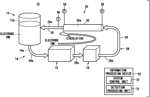
1. A viscosity measuring system, comprising:
a tank configured to store an electrode ink;
a flow pathway connected to the tank and in which the electrode ink is capable of flowing;
an external force applying unit disposed in the flow pathway and configured to apply an external force to the electrode ink;
a pump disposed in the flow pathway and configured to be capable of controlling a flow velocity or a flow rate of the electrode ink;
a first pressure detection unit disposed in the flow pathway, and configured to detect a pressure of the electrode ink flowing through the flow pathway;
a second pressure detection unit disposed in a portion in the flow pathway on a more downstream side than the first pressure detection unit, and configured to detect the pressure of the electrode ink flowing through the flow pathway; and
a detection processing unit configured to calculate a viscosity of the electrode ink based on the pressure detected by the first pressure detection unit and the pressure detected by the second pressure detection unit, wherein
the external force applying unit comprises a coating unit configured to coat a substrate material with the electrode ink; and
the first pressure detection unit is disposed in a portion in the flow pathway between the pump and the coating unit.
|