| CPC G01B 11/002 (2013.01) [G02B 6/02 (2013.01); G02B 6/262 (2013.01)] | 16 Claims |

|
1. A detector (112) for determining a position of at least one object (114), the detector (112) comprising:
at least one transfer device (130), wherein the transfer device (130) has at least one focal length in response to the at least one incident light beam propagating from the object (114) to the detector (112), wherein the transfer device (130) has at least one optical axis (142);
at least one illumination source (144) adapted to generate at least one light beam (146) for illuminating the object (114), wherein an exit pupil of the illumination source (144) is displaced from the optical axis (142) by a distance BL, wherein the illumination source (144) has a geometrical extend G in a range 3·10−4 mm2·sr≤G≤3.3 mm2·sr; wherein the illumination source (144) comprises at least one optical sender fiber (118) for illuminating the object (114);
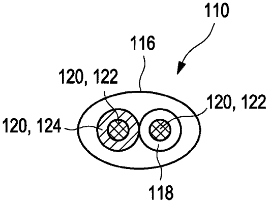
at least one first optical receiving fiber (120, 126) and at least one second optical receiving fiber (120, 124), wherein each of the optical receiving fibers (120, 126, 128) comprises at least one cladding (136) and at least one core (134), wherein the first optical receiving fiber (120, 122) has a core diameter of d1, wherein the second optical receiving fiber (120, 124) has a core diameter of d2, wherein the ratio d1/BL is in a range 0.000318≤d1/BL≤6.83, and/or wherein the ratio d2/BL is in a range 0.000318≤d2/BL≤6.83; wherein an entrance face of at least one of the optical receiving fibers (120, 126, 124) is arranged such that a variance over distance dependence of the combined signal is maximal, wherein the entrance face of at least one of the optical receiving fibers (120, 126, 124) is positioned as such that a combined signal Qfar at large object distances and a combined signal Qclose at small object distances have a maximum variation
 wherein rCocObject,close is a radius of the circle of confusion at small object distances and rCocObject,far is a radius of the circle of confusion at large object distances, wherein zO is a detectable distance range between the entrance face of at least one of the optical receiving fibers (120, 126, 124) and the object, zs is a distance between the transfer device (130) and the entrance face of at least one of the optical receiving fibers (120, 126, 124) and zi is a position of the focused image behind the transfer device (130), which depends on the position of the object zo;
at least two optical sensors (126, 128), wherein at least one first optical sensor (126) is arranged at an exit end of the first optical receiving fiber (120, 122) and at least one second optical sensor (128) is arranged at an exit end of the second optical receiving fiber (120, 124), wherein each optical sensor (126, 128) has at least one light sensitive area (147), wherein each optical sensor (126, 128) is designed to generate at least one sensor signal in response to an illumination of its respective light-sensitive area (148) by a light beam having passed through the respective optical receiving fiber (120, 122, 124); and
at least one evaluation device (150) being configured for determining at least one longitudinal coordinate z of the object (114) by evaluating a combined signal Q from the sensor signals.
|