| CPC F28D 9/0068 (2013.01) [F28D 9/00 (2013.01); F28F 9/0282 (2013.01)] | 7 Claims |

|
1. A heat exchanger, comprising;
a plurality of rows of media guiding ducts arranged to pass a media flow along inner, mutually facing boundary walls thereof;
a plurality of rows of fluid ducts arranged to pass fluid to be temperature-controlled, the fluid ducts being at least in part located in pairs spaced from each other and accommodating at least one row of the media guiding ducts between the fluid ducts of the pairs;
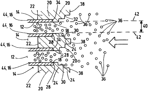
a free rectangular end face without a coating forming a rectangular media inlet exposed to a media flow, each of two opposite sides of the end face having first and second main struts each forming a support structure and being a hollow box forming a collection chamber for a liquid to transport heat, opposite axial ends of the fluid ducts opening in fluid communication with an inside of the respective collection chamber;
at least some of the fluid ducts having deflectors capable of routing contaminant particles entrained in medium flow through the end face at least in part away from the fluid ducts in directions of the media guiding ducts, each of the deflectors being formed by an elongated flow profile part being arranged on a free end face of the respective fluid duct, closing the respective fluid duct outwardly towards an environment and projecting beyond the respective fluid duct, each of the flow profile parts also including a guide part and a plug-in part connected in one piece to the guide part and inserted into the respective fluid duct, the guide part of each of the flow profile parts projecting forwardly from a plane of a free end face of inlets of the media guiding ducts and having converging lateral surfaces extending along a stepped course and ending in a narrow end surface; and
two mutually opposite steps being formed at the transition between the guide part and the plug-in part of each of the flow profile parts allowing the flow profile part to sit on the adjacent end faces of the respective fluid duct without spacing, each of the flow profile parts not projecting at any point into a free opening cross section defined by an extension of inner, mutually facing boundary walls the respective media duct and by the media inlet.
|