| CPC F25B 41/20 (2021.01) [F25B 13/00 (2013.01); F16K 11/065 (2013.01); F25B 2313/02741 (2013.01); F25B 2600/2513 (2013.01); F25B 2600/2519 (2013.01)] | 10 Claims |

|
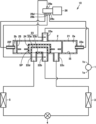
1. A refrigeration cycle apparatus comprising:
a compressor configured to compress refrigerant;
a four-way valve connected to the compressor;
a first outdoor heat exchanger connected to the four-way valve;
a first expansion valve connected to the first outdoor heat exchanger; and
an indoor heat exchanger connected to the first expansion valve and the four-way valve,
the four-way valve being configured to switch between passing the refrigerant compressed by the compressor to the first outdoor heat exchanger and passing the refrigerant compressed by the compressor to the indoor heat exchanger,
the four-way valve comprising
a casing having an inner surface,
a first flow channel and a second flow channel disposed in the casing, and
a flow channel switching piston and a wall portion disposed in the casing,
the flow channel switching piston being configured to slide along the inner surface to switch between passing the refrigerant through the first flow channel and passing the refrigerant through the second flow channel,
the wall portion being configured to slide along the inner surface together with the flow channel switching piston, the wall portion being disposed with a space between the flow channel switching piston and the wall portion to cover the flow channel switching piston.
|