| CPC F25B 25/02 (2013.01) [B01D 1/0082 (2013.01); B01D 1/26 (2013.01); B01D 3/007 (2013.01); B01D 5/006 (2013.01); C02F 1/043 (2013.01); C02F 1/048 (2013.01); F25B 41/24 (2021.01); F25B 41/325 (2021.01); C02F 2201/005 (2013.01); C02F 2303/10 (2013.01); F25B 2600/2513 (2013.01)] | 9 Claims |

|
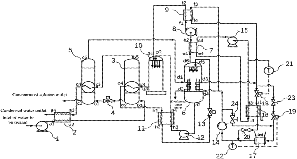
1. A water treatment system of coupling a heat pump with multi-effect evaporation, comprising a multi-effect evaporation circulation system, a lithium bromide absorption-type heat pump circulation system and a compression-type heat pump circulation system, wherein the multi-effect evaporation circulation system includes a first centrifugal pump (1), a pre-heater (2), a first-effect evaporator (3), a first pressure reducing valve (4), and a second-effect evaporator (5); water to be treated is connected to an inlet of the first centrifugal pump (1) through a pipeline, an outlet of the first centrifugal pump (1) is connected to an inlet (a1) of the pre-heater (2) through a pipeline, an outlet (a2) of the pre-heater (2) is connected to a solution inlet (b1) of the first-effect evaporator (3) through a pipeline, a solution outlet (b2) of the first-effect evaporator (3) is connected to a solution inlet (c1) of the second-effect evaporator (5) through the first pressure reducing valve (4), and a concentrated solution in the second-effect evaporator (5) is discharged from a concentrated solution outlet (c2), a vapor outlet (b5) of the first-effect evaporator (3) is connected to a vapor inlet (c3) of the second-effect evaporator (5) through a pipeline, and a condensed water outlet (c4) of the second-effect evaporator (5) is connected to a condensed water inlet (a3) of the pre-heater (2) through a pipeline, and a condensed water in the pre-heater (2) is discharged from an outlet (a4);
the lithium bromide absorption-type heat pump circulation system includes a generator (6), a condenser (7), a second centrifugal pump (8), a first evaporator (9), an absorber (10), a solution heat exchanger (11), a third centrifugal pump (12), and a second pressure reducing valve (13), a vapor inlet (d1) of the generator (6) is connected to a vapor outlet (c5) of the second-effect evaporator (5) through a pipeline, a condensed water of the generator (6) is discharged from an outlet (d2), an upper vapor outlet (d6) of the generator (6) is connected to a vapor inlet (e1) of the condenser (7), an outlet (e2) of the condenser (7) is connected to a water inlet (f1) of the first evaporator (9) through pipelines via the second centrifugal pump (8), a vapor outlet (f2) of the first evaporator (9) is connected to a top vapor inlet (g1) of the absorber (10), a bottom concentrated solution outlet (d7) of the generator (6) is connected to an inlet (h3) of the solution heat exchanger (11) via the third centrifugal pump (12), an outlet (h4) of the solution heat exchanger (11) is connected to a solution inlet (g2) of the absorber (10), a solution inlet (h1) of the solution heat exchanger (11) is connected to a solution outlet (b4) of the first-effect evaporator (3) through a pipeline, a solution outlet (h2) of the solution heat exchanger (11) is connected to a solution inlet (d5) of the generator (6) via the second pressure reducing valve (13), and a dilute solution outlet (g3) of the absorber (10) is connected to an inlet (b3) of the first-effect evaporator (3); and
the compression-type heat pump circulation system includes a compressor (14), a fourth centrifugal pump (15), a second evaporator (16), a third evaporator (17), a first throttle valve (18), a second throttle valve (19), and an evaporation pressure regulating valve (20), an outlet of the compressor (14) is connected to both a refrigerant inlet (d4) of the generator (6) and a refrigerant inlet (f3) of the first evaporator (9), a refrigerant outlet (d3) of the generator (6) and a refrigerant outlet (f4) of the first evaporator (9) are converged by pipelines, and then connected to both an inlet of a first cut-off valve (23) and an inlet of the first throttle valve (18), an outlet of the first throttle valve (18) is connected to a solution inlet (i1) of the second evaporator (16), a solution outlet (i2) of the second evaporator (16) is connected to an inlet of the evaporation pressure regulating valve (20), an outlet of the first cut-off valve (23) is connected to an inlet of the second throttle valve (19) through a pipeline, an outlet of the second throttle valve (19) is connected to an inlet of the third evaporator (17), an outlet of the third evaporator (17) and an outlet of the evaporation pressure regulating valve (20) are jointly connected to the compressor (14) through pipelines, an outlet of the fourth centrifugal pump (15) is connected to an outlet (e3) of the condenser (7), an outlet (e4) of the condenser (7) is connected to an inlet (i4) of the second evaporator (16), and an outlet (i3) of the second evaporator (16) is connected to an inlet of the fourth centrifugal pump (15).
|