| CPC F25B 25/00 (2013.01) [F25B 9/008 (2013.01); F25B 21/00 (2013.01); F25B 41/40 (2021.01); F25B 2321/002 (2013.01); F25B 2400/0403 (2013.01); F25B 2400/05 (2013.01); F25B 2500/09 (2013.01); F25B 2500/18 (2013.01); F25B 2600/2501 (2013.01); F25B 2600/2513 (2013.01); F25B 2600/2515 (2013.01)] | 20 Claims |

|
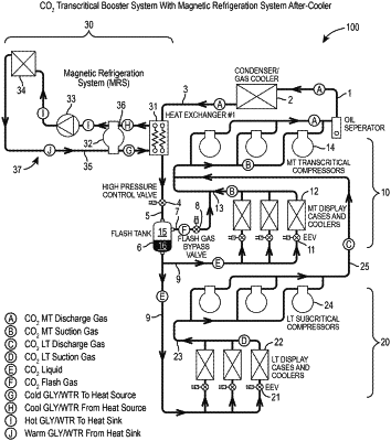
1. A refrigeration system comprising:
a refrigeration circuit comprising:
a gas cooler/condenser configured to remove heat from a refrigerant circulating within the refrigeration circuit and comprising an outlet through which the refrigerant exits the gas cooler/condenser;
a receiver comprising an inlet fluidly coupled to the outlet of the gas cooler/condenser and configured to collect the refrigerant from the gas cooler/condenser, the receiver further comprising an outlet through which the refrigerant exits the receiver; and
an evaporator comprising an inlet fluidly coupled to the outlet of the receiver and configured to receive the refrigerant from the receiver, the evaporator configured to transfer heat into the refrigerant circulating within the refrigeration circuit; and
a coolant circuit fluidly separate from the refrigeration circuit and comprising:
a heat exchanger configured to transfer heat from the refrigerant circulating within the refrigeration circuit into a coolant circulating within the coolant circuit, the heat exchanger comprising a coolant inlet through which the coolant enters the heat exchanger and a coolant outlet through which the coolant exits the heat exchanger;
a heat sink configured to remove heat from the coolant circulating within the coolant circuit, the heat sink comprising an inlet fluidly coupled to the coolant outlet of the heat exchanger and through which the coolant enters the heat sink, and comprising an outlet fluidly coupled to the coolant inlet of the heat exchanger and through which the coolant exits the heat sink; and
a magnetocaloric conditioning unit configured to transfer heat from the coolant within a first fluid conduit of the coolant circuit into the coolant within a second fluid conduit of the coolant circuit, the first fluid conduit fluidly coupling the coolant outlet of the heat exchanger to the inlet of the heat sink, and the second fluid conduit fluidly coupling the outlet of the heat sink to the coolant inlet of the heat exchanger.
|