| CPC F24F 3/1423 (2013.01) [F24F 2203/1004 (2013.01); F24F 2203/1036 (2013.01); F24F 2203/106 (2013.01); F24F 2203/1084 (2013.01)] | 20 Claims |

|
1. A desiccant configuration, comprising:
a plurality of similar structures;
a plurality of electrical heaters, an electrical heater of the plurality of electrical heaters being associated with a corresponding similar structure of the plurality of similar structures;
a plurality of switches, a switch of the plurality of switches selectively applying operating power to a corresponding electrical heater of the plurality of electrical heaters;
slip rings, the switches of the plurality of switches being positioned away from the slip rings, distinct from the slip rings, and separate from the slip rings, wherein operating power is selectively provided to the plurality of electrical heaters through the slip rings and the plurality of switches; and
a desiccant, the desiccant coating at least a portion of each similar structure of the plurality of similar structures.
|
|
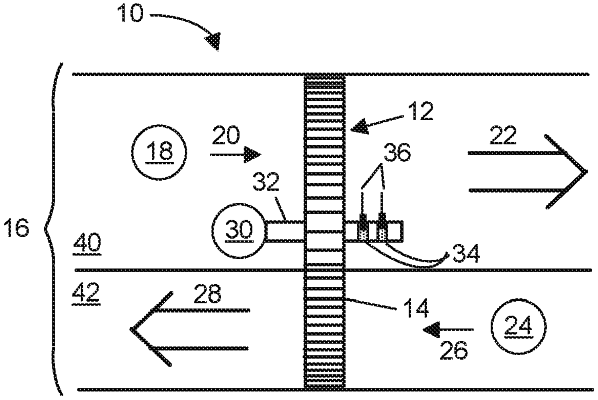
9. An air treatment apparatus, comprising:
a desiccant wheel, the desiccant wheel comprising:
a plurality of similar structures;
a plurality of electrical heaters, an electrical heater of the plurality of electrical heaters being associated with a corresponding similar structure of the plurality of similar structures;
a plurality of switches, a switch of the plurality of switches selectively applying operating power to a corresponding electrical heater of the plurality of electrical heaters; and
a desiccant, the desiccant coating at least a portion of each similar structure of the plurality of similar structures,
a plurality of activators controlling the plurality of switches;
slip rings, the switches of the plurality of switches being positioned away from the slip rings, distinct from the slip rings, and separate from the slip rings, wherein operating power is selectively provided to the plurality of electrical heaters through the slip rings and the plurality of switches a motor to rotate the desiccant wheel;
a shroud which separates the desiccant wheel into an active area and a regeneration area;
wherein an activator of the plurality of activators causes the switch of the plurality of switches to apply operating power to the corresponding electrical heater for the corresponding similar structure which is in the regeneration area; and
at least one fan which drives air through the desiccant wheel.
|
|
17. An air treatment apparatus, comprising:
a desiccant wheel, the desiccant wheel comprising:
a plurality of similar structures arranged about an axis of rotation;
a desiccant, the desiccant coating at least a portion of each similar structure of the plurality of similar structures;
a plurality of electrical heaters, an electrical heater of the plurality of electrical heaters being associated with a corresponding similar structure of the plurality of similar structures;
an adhesive to secure the desiccant to at least one of an electrical heater of the plurality of electrical heaters or to a similar structure of the plurality of similar internal structures;
a plurality of magnetic switches, a magnetic switch of the plurality of magnetic switches selectively applying operating power to a corresponding electrical heater of the plurality of electrical heaters; and
slip rings, the magnetic switches of the plurality of magnetic switches being positioned away from the slip rings, distinct from the slip rings, and separate from the slip rings, wherein operating power is selectively provided to the plurality of electrical heaters through the slip rings and the plurality of magnetic switches;
a motor to rotate the desiccant wheel about the axis of rotation;
a shroud which separates the desiccant wheel into an active area and a regeneration area;
a first magnet to apply a first magnetic field polarity;
a second magnet to apply a second magnetic field polarity;
wherein a magnetic switch of the plurality of magnetic switches applies operating power to the corresponding electrical heater of the plurality of electrical heaters when the first magnetic field polarity is applied, and does not apply operating power to the corresponding electrical heater when the second magnetic field polarity is applied;
a first fan which drives air through the active area of the desiccant wheel; and
a second fan which drives air through the regeneration area of the desiccant wheel.
|