| CPC F21S 41/265 (2018.01) [F21S 41/143 (2018.01); F21S 41/151 (2018.01)] | 20 Claims |

|
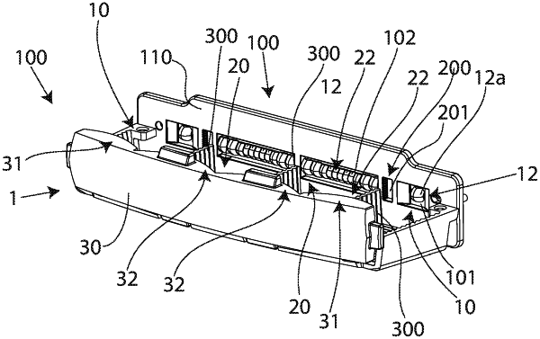
1. An illumination device (1) for a motor vehicle headlight, the illumination device comprising:
at least two illumination units (10, 20) arranged next to one another, wherein each illumination unit (10, 20) respectively comprises:
at least one light source (11, 21);
a transparent primary optical device (12, 22) associated with the at least one light source (11, 21); and
a transparent secondary optical device (31, 32),
wherein the primary optical device (11, 22) of each illumination unit (10, 20) is designed to direct the light emitted by the at least one light source (11, 21) associated therewith onto the secondary optical device (31, 32) in such a way that at least one light distribution is produced by the secondary optical device (31, 32) of the illumination unit (10, 20), wherein the illumination device (1) has a holding element (100), which holds the primary optical devices (12, 22) of the illumination units (10, 20), wherein the holding element (100) is formed by a body (110) made of a transparent material, wherein the body (110) has adjacent receiving through holes (101, 102), the (12, 22) is respectively arranged, the (12, 22) is respectively attached to at least one boundary surface (101a, 101b, 102a, 102b) of the receiving through hole (101, 102), which faces an adjacent receiving through hole (101, 102), wherein the receiving through holes (101, 102) are spaced apart from one another, and
wherein an overcoupling protective device (200) is arranged in the body (110) between two adjacent receiving through holes (101, 102), wherein the overcoupling protecting device (200) is formed by a through hole (201) in the body (110), wherein the through hole (201) of the overcoupling protective device (200) is delimited by two side faces (211, 212), which side faces (211, 212) face the receiving through holes (12, 22) in which the primary optical devices (12, 22) are arranged, and wherein at least one of the side faces (211, 212), namely that side face or those side faces (11, 12) whose opposite boundary surface of a receiving through hole (101, 102) is contacted by the primary optical device (12, 22) arranged in the receiving through hole (101, 102) has light deflection means (220, 230), which are designed to deflect at least part of the rays of light entering the body (110) from the primary optical device (12, 22) facing the side face (211, 212) and contacting the opposite boundary surface, and striking the side surface (211, 212), in such a way that this part of the rays of light does not enter the adjacent illumination unit (10, 20) or strike the secondary optical device (31, 32) of the adjacent illumination unit (10, 20).
|