| CPC F17C 13/001 (2013.01) [F17C 1/02 (2013.01); F17C 1/12 (2013.01); F17C 13/002 (2013.01); F17C 2201/0109 (2013.01); F17C 2201/035 (2013.01); F17C 2203/012 (2013.01); F17C 2203/0391 (2013.01); F17C 2203/0621 (2013.01); F17C 2221/012 (2013.01); F17C 2225/0161 (2013.01); F17C 2260/033 (2013.01); F17C 2270/0168 (2013.01)] | 13 Claims |

|
1. A liquid hydrogen storage tank assembly, comprising:
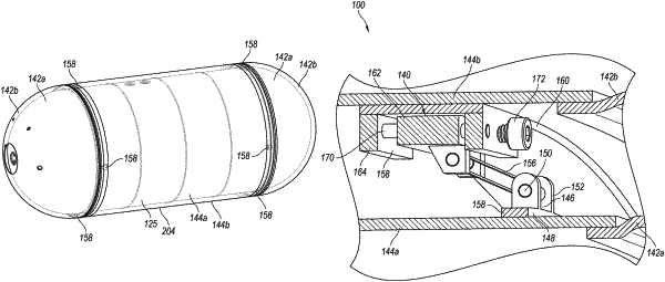
a rigid outer tank shell comprising a substantially cylindrical first body portion and substantially hemispherical first end caps affixed directly to opposing first end portions of the first body portion, the first body portion and the first end portions defining an internal volume;
outer girth rings affixed to the first end portions of the first body portion adjacent to a respective one of the first end caps;
an inner tank within the internal volume and forming a pressure vessel for containing liquid hydrogen fuel substantially at cryogenic temperature and at a pressurized state, the inner tank comprising a substantially cylindrical second body portion in the internal volume and fully surrounded by the first body portion, wherein the second body portion is substantially coaxially positioned within and spaced apart from the first body portion, the inner tank further comprising substantially hemispherical second end caps affixed directly to opposing second ends of the second body portion, wherein the second end caps are substantially coaxially positioned within and spaced apart from adjacent ones of the first end caps, wherein the inner tank is suspended in a substantially concentric arrangement within the outer tank shell to form an interstitial space between the inner tank and the outer tank shell;
inner girth rings affixed to the second end portions of the second body portion adjacent to a respective one of the second end caps, the inner girth rings being substantially concentrically arranged and radially inward from the outer girth rings;
a plurality of retention strap assemblies interconnecting the first and second body portions and suspending the inner tank in the interior volume within the outer tank shell and allowing for movement of the inner tank relative to the outer tank shell due to contraction or expansion of the inner tank, each retention strap assembly comprising a strap member configured to pivot and maintain a constant length and tension as the inner tank expands or contracts relative to the outer tank shell;
wherein a first group of the retention strap assemblies each comprise a first inner anchor portion directly connected to one of the inner girth rings and positioned in the interstitial space between the first and second body portions, and comprise a first outer anchor portion directly connected to one of the outer girth rings and positioned in the interstitial space between the first and second body portions, wherein each first outer anchor portion is spaced at least partially longitudinally apart from a respective one of the first inner anchor portions;
wherein a second group of the retention strap assemblies each comprise a second inner anchor portion directly connected to the other one of the inner girth rings and positioned in the interstitial space, and the second group of retention strap assemblies comprise a second outer anchor portion directly connected to the other one of the outer girth rings and positioned in the interstitial space, wherein each first outer anchor portion is spaced at least partially longitudinally apart from a respective one of the first inner anchor portions;
wherein first strap members of the first group of retention strap assemblies are directly connected to and extend between adjacent first inner and outer anchor portions, and second strap members of the second group of retention strap assemblies are directly connected to and extend between adjacent second inner and outer anchor portions; and
wherein the first inner or outer anchor portions of each retention strap assembly comprise an adjustable translatable carriage coupled to the strap member, wherein the translatable carriage is movable longitudinally relative to the inner and outer cylindrical bodies to control tension in the strap member.
|