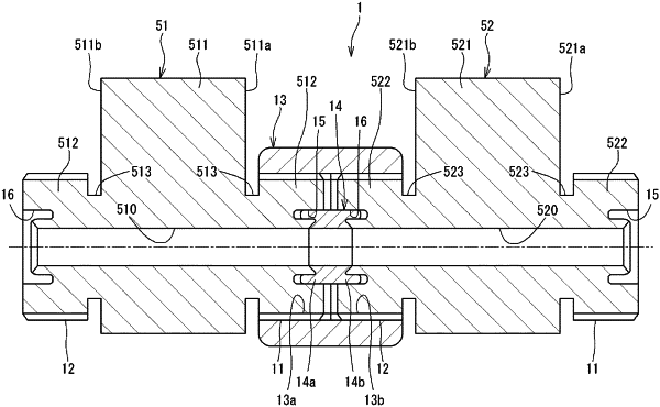
| CPC F16L 19/0212 (2013.01) [F16L 15/04 (2013.01); F16L 17/06 (2013.01)] | 10 Claims |

|
1. A flow passage joint structure for connecting flow passage holes formed in two fluid devices, respectively, to each other, the flow passage joint structure comprising:
a first external thread portion formed, at an end portion of one fluid device of the two fluid devices, radially outward of the flow passage hole of the one fluid device;
a second external thread portion formed, at an end portion of the other fluid device of the two fluid devices, radially outward of the flow passage hole of the other fluid device;
a union nut having a first internal thread portion to be screwed to the first external thread portion, on one side in an axial direction thereof, and having a second internal thread portion to be screwed to the second external thread portion, on another side in the axial direction thereof; and
a sealing member configured to seal a connection portion between the flow passage holes in the two fluid devices on a radially inner side of the union nut when the first internal thread portion is screwed to the first external thread portion and the second internal thread portion is screwed to the second external thread portion, wherein
each of the first external thread portion and the first internal thread portion is one of a right-hand thread and a left-hand thread, and
each of the second external thread portion and the second internal thread portion is the other of the right-hand thread and the left-hand thread,
a thread start position of the first external thread portion and a thread start position of the second external thread portion are set at a same position in a circumferential direction, and
a thread start position of the first internal thread portion and a thread start position of the second internal thread portion are set at a same position in the circumferential direction,
the flow passage joint structure comprising:
a first mark portion provided to the one fluid device and indicating the thread start position of the first external thread portion;
a second mark portion provided to the other fluid device and indicating the thread start position of the second external thread portion; and
a third mark portion provided to the union nut and indicating a position shifted, in a tightening direction of the union nut by a predetermined angle, from at least one of the thread start position of the first internal thread portion and the thread start position of the second internal thread portion.
|