| CPC F16H 61/12 (2013.01) [F16H 2061/1224 (2013.01); F16H 2061/1252 (2013.01); F16H 2061/1264 (2013.01)] | 2 Claims |

|
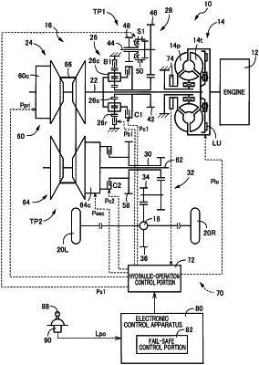
1. A power transmission apparatus for a vehicle, comprising:
a fluid transmission device having a lockup clutch;
an automatic transmission including: an input shaft to which a power is to be transmitted from a drive power source through the fluid transmission device; an output shaft; a hydraulically-operated forward-driving engagement device for forward driving of the vehicle; and a hydraulically-operated reverse-driving engagement device for reverse driving of the vehicle; and
a hydraulic control unit including a first switching valve, a third switching valve and a failure switching valve that are provided for switching fluid paths, and a lockup hydraulic control valve and a second hydraulic control valve that are provided for controlling various hydraulic pressures,
wherein the first switching valve is configured, when being placed in a first connection state thereof, to output a line pressure that is a source pressure for the various hydraulic pressures, as a D-range pressure for the forward driving of the vehicle, and is configured, when being placed in a second connection state thereof, to output a control pressure of the lockup hydraulic control valve, as a failure pressure to the failure switching valve,
wherein the third switching valve is configured, when being placed in a first connection state thereof, to output the control pressure of the lockup hydraulic control valve to a lockup engagement passage for controlling an engagement pressure of the lockup clutch, and is configured, when being placed in a second connection state thereof, to output the control pressure of the lockup hydraulic control valve to the reverse-driving engagement device,
wherein the failure switching valve is configured, when being placed in a first connection state thereof, to output the D-range pressure that is supplied with the first switching valve being placed in the first connection state thereof, to the second hydraulic control valve, and is configured, when being placed in a second connection state thereof, to output the line pressure that is supplied through a path separate from the D-range pressure, as an evacuation pressure for evacuation driving of the vehicle, to the second hydraulic control valve, and to output the failure pressure that is supplied with the first switching valve being placed in the second connection state thereof, to a lockup release passage for forcibly releasing the lockup clutch,
wherein the failure switching valve is mechanically placed in the second connection state thereof when the failure pressure is supplied to the failure switching valve, and is mechanically placed in the first connection state thereof when the failure pressure is stopped to be supplied to the failure switching valve,
wherein the second hydraulic control valve is disposed between the failure switching valve and the forward-driving engagement device, and is configured to control one of the D-range pressure and the evacuation pressure that are supplied from the failure switching valve, and to output a hydraulic output that is a controlled one of the D-range pressure and the evacuation pressure to the forward-driving engagement device for thereby controlling an operation state of the forward-driving engagement device,
the power transmission apparatus comprising:
a control apparatus configured, in event of detection of a predetermined anomaly with a possibility of a failure in which the lockup hydraulic control valve is stuck in a hydraulic output state thereof, to establish a fail safe mode in which the first switching valve is placed in the second connection state thereof, the third switching valve is placed in the first connection state thereof, and the failure switching valve is placed in the second connection state based on the failure pressure that is a hydraulic output of the lockup hydraulic control valve, whereby the lockup clutch is held in a released state thereof based on the failure pressure supplied to the lockup release passage from the failure switching valve, and the forward-driving engagement device is engaged by a control pressure of the second hydraulic control valve, for thereby enabling the forward driving,
wherein the control apparatus is configured, upon selection of a neutral range for cutting off transmission of the power in the event of the detection of the predetermined anomaly, to place the first switching valve in the second connection state thereof, place the third switching valve in the first connection state thereof, and stop the hydraulic output of the lockup hydraulic control valve and the hydraulic output of the second hydraulic control valve.
|