| CPC F16D 3/20 (2013.01) [F16D 1/027 (2013.01); F16D 2200/0052 (2013.01); Y10S 285/915 (2013.01); Y10T 403/477 (2015.01)] | 14 Claims |

|
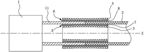
1. A shaft tube joint structure of a drive shaft, comprising:
an extension tube, having an inner cylindrical surface of the extension tube and an outer cylindrical surface of the extension tube;
a shaft tube, abutted to the extension tube in an axis direction and having an inner cylindrical surface of the shaft tube and an outer cylindrical surface of the shaft tube, wherein the inner cylindrical surface of the extension tube is abutted to the inner cylindrical surface of the shaft tube, and the outer cylindrical surface of the extension tube is abutted to the outer cylindrical surface of the shaft tube;
a convex tube, having an outer circumferential surface of the convex tube, sleeved in the extension tube and the shaft tube at an abutting position between the extension tube and the shaft tube in the axis direction, and located inside the inner cylindrical surface of the extension tube and the inner cylindrical surface of the shaft tube, wherein an inner seam having a variable gap size distribution in the axis direction is formed between the outer circumferential surface of the convex tube and the inner cylindrical surface of the extension tube as well as the inner cylindrical surface of the shaft tube at the abutting position between the extension tube and the shaft tube;
an inner adhesive rubber ring, filled in the inner seam, wherein a thickness of the inner adhesive rubber ring has a variable thickness size distribution in the axis direction;
a concave tube, having an inner circumferential surface of the concave tube, sleeved on the extension tube and the shaft tube at the abutting position between the extension tube and the shaft tube in the axis direction, and located outside the outer cylindrical surface of the extension tube and the outer cylindrical surface of the shaft tube, wherein an outer seam having a variable gap size distribution in the axis direction is formed between the inner circumferential surface of the concave tube and the outer cylindrical surface of the extension tube as well as the outer cylindrical surface of the shaft tube at the abutting position between the extension tube and the shaft tube; and
an outer adhesive rubber ring, filled in the outer seam, wherein a thickness of the outer adhesive rubber ring has a variable thickness size distribution in the axis direction;
wherein a diameter at a middle part of the outer circumferential surface of the convex tube is greater than diameters at two ends of the outer circumferential surface of the convex tube.
|