| CPC F16D 13/56 (2013.01) [F16D 13/71 (2013.01); F16D 13/74 (2013.01); F16D 2013/565 (2013.01); F16D 2300/06 (2013.01)] | 7 Claims |

|
1. A clutch device to allow or interrupt transfer of a rotation driving force of an input shaft to an output shaft, the clutch device comprising:
a clutch center housed in a clutch housing configured to be rotationally driven by the input shaft and holding a plurality of input-side rotating plates rotatable together with and axially displaceable relative to the clutch housing, the clutch center configured to be rotationally driven together with the output shaft; and
a pressure plate movable toward or away from and rotatable relative to the clutch center, holding a plurality of output-side rotating plates rotatable together with and axially displaceable relative to the pressure plate, and operable to press the input-side rotating plates and the output-side rotating plates, the input-side rotating plates and the output-side rotating plates being alternately arranged; wherein
assuming directions in which the pressure plate moves toward or away from the clutch center are movement directions, a direction in which the pressure plate moves toward the clutch center is a first direction, and a direction in which the pressure plate moves away from the clutch center is a second direction;
the pressure plate includes:
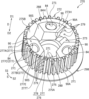
a ring-shaped outer peripheral wall extending along the movement directions;
a plurality of pressure-side fitting teeth holding the output-side rotating plates, projecting radially outward from an outer peripheral surface of the outer peripheral wall, and arranged in circumferential directions; and
an oil channel located in an end portion of at least one of the pressure-side fitting teeth in the first direction; and
the oil channel allows clutch oil flowing at least at an inner peripheral surface of the outer peripheral wall to be discharged to outside of the pressure plate.
|