| CPC F02P 3/0442 (2013.01) [F02P 17/12 (2013.01); F02P 2017/125 (2013.01)] | 11 Claims |

|
1. An electronic ignition system to detect a misfire in an internal combustion engine, the system comprising:
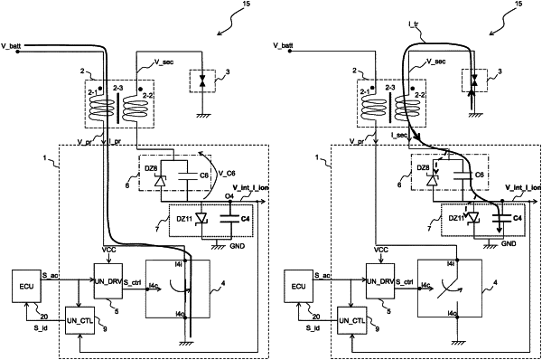
a coil having a primary winding with a first terminal connected to a battery voltage and having a secondary winding with a first terminal connected to a spark plug;
an electronic control device comprising:
a high-voltage switch connected in series to a primary winding of a coil and configured to switch between a closed position and an open position;
a driving unit configured to:
control a closure of the high-voltage switch during a phase of charging energy into the primary winding;
control the opening of the high-voltage switch during a phase of transfer of energy from the primary winding to a secondary winding of the coil and during a phase of measurement of an ionization current subsequent to the phase of transfer of energy, wherein said ionization current is generated by ions produced during a process of combustion of a comburent-combustible mixture in a combustion chamber of a cylinder of the engine by means of a spark generated by a spark plug in the phase of transfer of energy;
a bias circuit configured to generate said ionization current during the phase of measurement of the ionization current, wherein said bias circuit is connected in series to a second terminal of the secondary winding;
an integrating circuit interposed between the bias circuit and a reference voltage;
wherein said integrating circuit is configured to:
completely discharge towards a substantially null value by means of the current flowing through the secondary winding during the phase of transfer of energy from the primary winding to the secondary winding;
charge, by means of the ionization current generated by the bias circuit, to a value different from zero during the phase of measurement of the ionization current so as to measure a value of the integral of the ionization current, in a case of a correct ignition of the comburent-combustible mixture;
maintain a substantially null charge during the phase of measurement of the ionization current so as to measure a substantially null value of the integral of the ionization current, in the case of a misfire of the comburent-combustible mixture;
wherein the primary winding has a second terminal connected to the high-voltage switch;
an electronic control unit connected to the driving unit of the electronic control device and comprising an output terminal adapted to generate an ignition signal having a first value indicating a start of the phase of charging the primary winding and having a second value indicating the start of the phase of transfer of energy from the primary winding to the secondary winding,
and wherein the driving unit is further configured to receive the ignition signal and generate, as a function thereof, a control signal for opening and closing the high-voltage switch, wherein the electronic device further comprises a local control unit connected to the integrating circuit and to the electronic control unit,
wherein the local control unit comprises:
a first input terminal adapted to receive the ignition signal;
a second input terminal adapted to receive an integrating voltage signal representative of the voltage across the integrating circuit;
an output terminal adapted to generate a combustion monitoring signal carrying, during the phase of charging energy, a voltage pulse having a length increasing with the increase of the value of the integrating voltage signal in the phase of measurement of the ionization current of a previous cycle;
wherein the electronic control unit further comprises an input terminal adapted to receive the combustion monitoring signal,
and wherein the electronic control unit is configured to detect a presence or an absence of a misfire as a function of a comparison between the length of said voltage pulse and an ignition threshold.
|