| CPC F02C 7/232 (2013.01) [F23R 3/28 (2013.01); F05D 2220/32 (2013.01); F05D 2240/36 (2013.01)] | 2 Claims |

|
1. A liquid fuel injection body comprising:
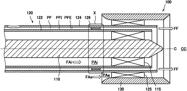
an annular fuel passage extending in an axial direction and provided inside the liquid fuel injection body,
wherein the fuel passage is defined by a fuel passage outer wall located outward in a radial direction and a fuel passage inner wall located inward in the radial direction, and a plurality of throttle passages disposed discretely in a circumferential direction are provided at a portion of the fuel passage on an upstream side with respect to a downstream end of the fuel passage,
each of the throttle passages is defined by a throttle passage outer wall located outward in the radial direction and formed as a cylindrical surface, a throttle passage inner wall located inward in the radial direction, and two throttle passage side walls connecting end portions of the throttle passage outer wall and the throttle passage inner wall in the circumferential direction, and
the throttle passage outer wall and the fuel passage outer wall are flush whereas the throttle passage inner wall and the fuel passage inner wall are not flush, and
a region with high surface roughness, a spiral-shaped groove, or a spiral-shaped projecting portion is provided at least at a portion of the fuel passage outer wall on a downstream side with respect to the throttle passage.
|