| CPC F01D 5/186 (2013.01) [F05D 2220/32 (2013.01); F05D 2240/30 (2013.01); F05D 2260/202 (2013.01)] | 10 Claims |

|
1. A turbine rotor blade, comprising
a leading edge portion having a plurality of cooling holes,
wherein the plurality of cooling holes includes:
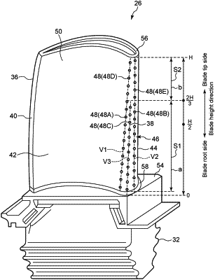
m cooling holes arranged in a first range in a blade height direction, where m is an integer of 2 or more; and
n cooling holes arranged in a second range on a blade tip side of the first range in the blade height direction, where n is an integer of 2 or more, and
wherein n/b<m/a is satisfied, where a is a dimension of the first range in the blade height direction, and b is a dimension of the second range in the blade height direction,
wherein the plurality of cooling holes includes:
a plurality of cooling hole rows each of which is arranged along the blade height direction in the first range; and
at least one cooling hole row which or each of which is arranged along the blade height direction in the second range, and
wherein the number of cooling hole rows in the second range is less than the number of cooling hole rows in the first range,
wherein the plurality of cooling hole rows in the first range includes a pressure-side cooling hole row formed on a pressure surface and a suction-side cooling hole row formed on a suction surface,
wherein the pressure-side cooling hole row in the first range is arranged along a first virtual line which is linear,
wherein the suction-side cooling hole row in the first range is arranged along a second virtual line which is linear, and
wherein when X is defined as a distance between the first virtual line and the second virtual line at a same position in the blade height direction on the blade surface, the distance X decreases as the position in the blade height direction changes from the first range to the second range.
|