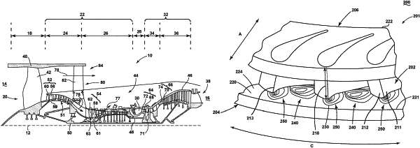
| CPC F01D 5/02 (2013.01) [F01D 5/14 (2013.01); F05D 2220/30 (2013.01)] | 18 Claims |

|
1. A turbine engine stage for at least one of a compressor or a turbine, the turbine engine stage comprising:
a plurality of airfoils extending between an inner band and an outer band, each airfoil in the plurality of airfoils having an outer wall defining a pressure side and a suction side, with the outer wall extending between a leading edge and a trailing edge; and
an intervening flow passage defined between a first airfoil and a second airfoil in the plurality of airfoils;
wherein at least one of the inner band or the outer band includes a platform extending along an axial direction between a forward edge and an aft edge, with the platform having a contoured flow surface comprising:
a trough extending along at least a portion of the pressure side of the first airfoil and having a local minimum proximate the leading edge of the first airfoil; and
a bulge positioned in the intervening flow passage and having a local maximum spaced from each of the first airfoil and the second airfoil;
wherein each of the bulge and the trough are positioned aft of the forward edge of the platform.
|