| CPC E06B 9/307 (2013.01) [E06B 9/32 (2013.01); E06B 2009/285 (2013.01)] | 20 Claims |

|
1. A method of providing a window covering, comprising:
providing a tilt mechanism that is positionable in a first rail of the window covering, the tilt mechanism comprising:
a tilt shaft gear having an aperture, a portion of a tilt shaft being passable through the tilt shaft gear via the aperture of the tilt shaft gear such that rotation of the tilt shaft gear causes the tilt shaft to rotate when the tilt shaft is within the aperture;
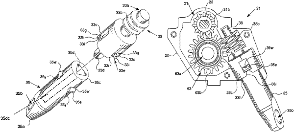
a control gear positioned adjacent the tilt shaft gear such that rotation of the control gear causes the tilt shaft gear to rotate, an upper end of the control gear having at least one tooth, a lower end of the control gear being opposite the upper end of the control gear, the lower end of the control gear defining a coupling mechanism having a plurality of prongs that extend around a central projection;
a wand connector having an upper end and a lower end opposite the upper end, the upper end of the wand connector having a hole in communication with a channel defined in a body of the wand connector such that the central projection is insertable into the wand connector via the hole and the channel; a plurality of protrusions extending from the body of the wand connector around a periphery of the body of the wand connector, each one of the protrusions configured to have an upper surface configured to contact a respective one of the prongs to resiliently move the prongs away from the central projection as the central projection is inserted into the body of the wand connector, wherein the respective upper surface of each one of the protrusions extends linearly away from the body of the wand connector so that the protrusions guide the prongs away from the central projection when the prongs are moved along the protrusions each one of the protrusions have a bottom surface configured to contact a portion of the respective one of the prongs after a distal end of the respective prong passes over the upper surface of each one of the protrusions to interlock with an upper flat portion of the respective prong;
passing the central projection into the hole of the upper end of the wand connector to insert the central projection into the channel;
causing the prongs to engage the protrusions to resiliently move the prongs away from the central projection;
interlocking the respective bottom surfaces of the protrusions with upper surfaces of the respective distal ends of the prongs after the prongs are passed lowest ends of the the respective upper surfaces of the protrusions to affix the wand connector to the control gear.
|