| CPC E05B 77/06 (2013.01) [E05B 77/32 (2013.01); E05B 79/08 (2013.01)] | 10 Claims |

|
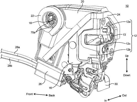
1. A door lock device comprising:
a latch that is pivotably supported by a latch shaft, and configured to engage with a striker for closing a door of a vehicle;
a ratchet configured to keep the latch engaged with the striker;
an outer lever that is pivotably supported by an outer lever shaft, and configured to link with an outer handle;
an open link that is displaceable between an unlocking position, a locking position, and an inertia engaging position that is between the unlocking position and the locking position by swinging, the open link being configured to
communicate a movement of the outer lever to the ratchet, thereby causing the ratchet to release an engagement of the latch, when the open link is at the unlocking position, and
disable the movement of the outer lever, when the open link is at the locking position or the inertia engaging position;
a first elastic member configured to bias the open link toward the unlocking position;
an inertia lever that is displaceable between a standby position and a blocking position by rotating along a plane perpendicular to a plane where the open link swings, the inertia lever having a center of gravity decentered from a rotational axis thereof;
a second elastic member configured to bias the inertia lever toward the standby position;
a fitting hole that is provided to an acting piece protruding from the inertia lever; and
a protrusion that is provided to the open link, and configured to project into a range of a trajectory of a movement of the fitting hole while the open link is at the unlocking position, wherein
when an inertial force equal to or greater than a set value is exerted in a direction from an interior to an exterior of a cabin of the vehicle while the open link is at the unlocking position,
the inertial force causes the inertia lever to rotate against a biasing force of the second elastic member,
the acting piece is caused to press the protrusion,
the open link is caused to swing against a biasing force of the first elastic member by the protrusion being pressed by the acting piece, and
the protrusion becomes fitted inside the fitting hole which achieves an inertia engagement configuration in which the inertia lever is kept at the blocking position and the open link is kept at the inertia engaging position.
|