| CPC E04H 15/28 (2013.01) [A45B 19/10 (2013.01); A45B 25/02 (2013.01); E04H 15/48 (2013.01); A45B 2023/0006 (2013.01)] | 11 Claims |

|
1. An apparatus, comprising:
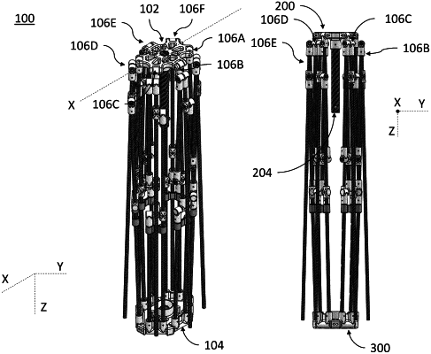
a first hub comprising a first plurality of recesses;
a second hub comprising a second plurality of recesses and an alignment guide;
a plurality of legs, wherein each leg is connected to the first hub and the second hub; and
a rod connected to the first hub and comprising a plurality of pins that are movable between an extended state and a retracted state, wherein in the extended state the plurality of pins protrude from the rod, and in a retracted state the plurality of pins are retracted within the rod,
wherein the first hub is movable relative to the second hub between a first state in which the rod is disposed above the alignment guide in an axial direction defined by an opening in the alignment guide and a second state in which a portion of the rod comprising the plurality of pins is located below the alignment guide in the axial direction,
wherein each of the plurality of legs includes a lower pivoting mechanism (LPM) and an upper pivoting mechanism (UPM),
wherein the upper pivoting mechanism includes a UPM lower joint and a UPM upper joint, and
wherein the UPM lower joint comprises a first UPM rotational coupler, a second UPM rotational coupler, a first UPM pass-through coupler, and a UPM connecting pin,
wherein the first UPM rotational coupler, the second UPM rotational coupler, and the first UPM pass-through coupler are connected by the UPM connecting pin to establish a rotational connection between the first UPM rotational coupler, the second UPM rotational coupler, and the first UPM pass-through coupler about an axis defined by the UPM connecting pin, and
wherein the second UPM rotational coupler is disposed between the first UPM rotational coupler and the first UPM pass-through coupler in an axial direction defined by the UPM connecting pin.
|