| CPC E03F 3/046 (2013.01) [E02B 11/005 (2013.01)] | 12 Claims |

|
1. A drainage channel comprising:
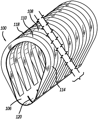
a main body having an upside-down pear-shaped cross section with a hollow interior having an interior top surface and an interior bottom surface, the hollow interior defined by two circular areas of different diameters stacked vertically and connected by two straight lines extending tangentially from each of the two circular areas, the two straight lines including a first straight line and a second straight line, the two circular areas including
a top circular area, and
a bottom circular area, the top circular area having a first diameter, and the bottom circular area having a second diameter, and the second diameter being smaller than the first diameter;
the main body further having a top surface, a first side surface, a second side surface, and a bottom surface, wherein the bottom surface is smooth,
the top surface having a top curvature across a width of the top surface corresponding to the interior top surface that is defined by the first diameter of the top circular area,
the first side surface being straight along a height of the first side surface and connecting the top surface and the bottom surface,
the second side surface disposed opposite the first side surface and being straight along a height of the second side surface and connecting the top surface and the bottom surface; and
the bottom surface having a bottom curvature across a width of the bottom surface corresponding to the interior bottom surface that is defined by the second diameter of the bottom circular area,
the main body including a plurality of drainage holes formed through the main body in the bottom surface of the main body, the drainage holes having a size and a shape configured to militate against debris and sedimentation entering the hollow interior of the main body, and the drainage holes also spaced at a distance so as to minimize a disturbance to laminar flow within the hollow interior of the main body, and water can only enter the hollow interior of the main body through the drainage holes in the bottom surface via hydraulic pressure, and
the main body further having a plurality of ribs formed on the top surface and the first and second side surfaces, the ribs providing flexibility to the drainage channel along a length of the drainage channel.
|