| CPC B66B 5/18 (2013.01) [B66B 5/044 (2013.01)] | 14 Claims |

|
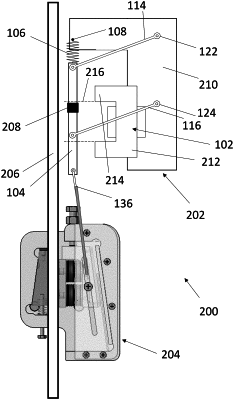
1. A frictionless electronic safety actuator (100; 202) for use in an elevator system, comprising:
a magnetic plate (104);
an electromagnet (102);
a linkage (136) that is actuatable so as to move a safety brake (204) into frictional engagement with an elevator guide rail (206), wherein the linkage (136) is attached to the magnetic plate (104), and wherein the magnetic plate (104) is moveable between a first position in which the linkage (136) is actuated and a second position in which the linkage (136) is not actuated; and
a biasing arrangement (106) arranged to apply a biasing force to the magnetic plate (104) to bias the magnetic plate (104) towards the first position;
wherein the electromagnet (102) is operable to selectively produce a magnetic force which acts upon the magnetic plate (104) in a first direction towards the electromagnet (102) and which is sufficient to overcome the biasing force to move the magnetic plate (104) away from the first position; and
wherein the frictionless electronic safety actuator (100; 202) further comprises a path-constraining arrangement (112) that constrains a path of movement of the magnetic plate (104) such that, when the magnetic force acts upon the magnetic plate (104), the magnetic plate (104) is constrained such that the magnetic plate (104) moves from the first position to the second position along the path of movement, wherein the second position is displaced relative to the first position in a direction that has a component perpendicular to the first direction;
wherein the biasing arrangement (106) is arranged to apply the biasing force directly to the magnetic plate (104).
|