| CPC B62D 3/12 (2013.01) [F16H 19/04 (2013.01); F16H 55/28 (2013.01)] | 9 Claims |

|
1. A steering device comprising:
a housing including a rack bar receiving portion, a pinion receiving portion, and a retainer receiving portion,
the rack bar receiving portion which has a cylindrical shape, and which is configured to receive a rod-shaped rack bar,
the pinion receiving portion which is connected to the rack bar receiving portion, and which is configured to receive a pinion shaft,
a first axis defined as an axis which passes through a center of the rack bar in a section perpendicular to a longitudinal direction of the rack bar, and which is parallel to the longitudinal direction of the rack bar,
the retainer receiving portion which has a cylindrical shape extending in a second axis perpendicular to the first axis, and which is configured to movably receive a retainer,
the second axis passing through a center of the retainer receiving portion in a section perpendicular to the second axis, and
the rack bar receiving portion disposed between the pinion receiving portion and the retainer receiving portion in a section perpendicular to the longitudinal direction of the rack bar;
the pinion shaft including a pinion teeth portion;
the rack bar having the rod shape, and including a rack bar main body portion, a rack teeth portion, and a rack back surface portion,
the rack teeth portion provided to the rack bar main body portion, and configured to be engaged with the pinion teeth portion, and
the rack back surface portion which is provided to the rack bar main body portion, which has an arc shape in the section perpendicular to the first axis, and which is formed on a side opposite to the rack teeth portion with respect to the first axis;
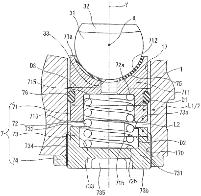
a spring holding member which is provided in the retainer receiving portion to be apart from the rack bar in the second axis direction, and which includes a spring holding member main body portion and a spring holding member abutment surface,
the spring holding member main body portion including a pair of end portions in the second axis direction, the pair of the end portions including a spring holding member first end portion and a spring holding member second end portion, and
the spring holding member abutment surface provided to the spring holding member first end portion near the rack bar;
a spring configured to urge the retainer toward the rack bar in the second axis direction, and the rack bar, the retainer, the spring, and the spring holding member being disposed in this order in the second axis direction;
the retainer including a retainer main body portion, a retainer abutment portion, and a retainer chamfering portion,
the retainer abutment portion which has an arc shape in a section that passes through the second axis, and that is perpendicular to the first axis, and which is configured to be abutted on the rack back surface portion,
the retainer main body portion including a pair of end portions in the second axis direction, the pair of the end portions including a retainer first end portion and a retainer second end portion,
the retainer chamfering portion provided on the retainer second end portion near the spring holding member, on a retainer second end portion outer circumference portion which is an outer circumference edge of the retainer main body portion in a section perpendicular to the second axis, and
the retainer chamfering portion formed at a portion which is nearest the spring holding member abutment surface in the retainer second end portion outer circumference portion in a section that passes through the second axis, and that is perpendicular to the first axis, when the retainer main body portion is inclined with respect to the second axis,
wherein the retainer chamfering portion is a round chamfering, and wherein when a bisector of an angle of the retainer second end portion is drawn in a section of the retainer chamfering portion which passes through the second axis, and which is perpendicular to the first axis, a center of a radius of curvature of the round chamfering of the retainer chamfering portion is positioned on the rack bar side of the bisector of the angle of the retainer second end portion.
|