US 11,938,851 B2
Seat frame for vehicle seat
Masayuki Hoshi, Tochigi (JP)
Assigned to TS TECH CO., LTD., Saitama (JP)
Filed by TS TECH CO., LTD., Saitama (JP)
Filed on Apr. 14, 2023, as Appl. No. 18/300,442.
Application 15/810,970 is a division of application No. 15/249,960, filed on Aug. 29, 2016, granted, now 9,815,397, issued on Nov. 14, 2017.
Application 15/249,960 is a division of application No. 14/424,312, granted, now 9,428,084, issued on Aug. 30, 2016, previously published as PCT/JP2012/072387, filed on Sep. 3, 2012.
Application 18/300,442 is a continuation of application No. 17/571,581, filed on Jan. 10, 2022, granted, now 11,628,754.
Application 17/571,581 is a continuation of application No. 17/222,103, filed on Apr. 5, 2021, abandoned.
Application 17/222,103 is a continuation of application No. 16/834,056, filed on Mar. 30, 2020, granted, now 10,967,770, issued on Apr. 6, 2021.
Application 16/834,056 is a continuation of application No. 16/389,387, filed on Apr. 19, 2019, granted, now 10,604,044, issued on Mar. 31, 2020.
Application 16/389,387 is a continuation of application No. 15/810,970, filed on Nov. 13, 2017, granted, now 10,266,087, issued on Apr. 23, 2019.
Prior Publication US 2023/0249595 A1, Aug. 10, 2023
Int. Cl. B60N 2/68 (2006.01); B60N 2/02 (2006.01); B60N 2/22 (2006.01); B60N 2/427 (2006.01)
CPC B60N 2/682 (2013.01) [B60N 2/22 (2013.01); B60N 2/42709 (2013.01); B60N 2/68 (2013.01); B60N 2/02258 (2023.08)] 18 Claims
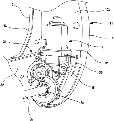
OG exemplary drawing
 
1. A vehicle seat comprising:
a seat back frame,
wherein:
the seat back frame comprises
side frames that are disposed at both ends of the seat back frame in a seat width direction of the vehicle seat,
a lower member frame that connects lower ends of the side frames and is formed of a plate-shaped member,
a reclining mechanism that comprises a rotation shaft and is configured to pivot the seat back with respect to a seat cushion of the vehicle seat, and
an actuator configured to be driven to rotate the rotation shaft of the reclining mechanism;
an upper flange is provided at an upper portion of the lower member frame, wherein the upper flange is formed by bending an upper end portion of the lower member frame;
each of the side frames includes a side wall and a rear wall that extends inward in the seat width direction from a rear end of the side wall;
a rear wall side flange is provided at an inner end of the rear wall in the seat width direction;
the upper flange extends to an outside of the rear wall side flange in the seat width direction; and
the upper flange is located at a position that overlaps the actuator in an up and down direction.