| CPC B60B 19/003 (2013.01) [B60B 19/125 (2013.01)] | 17 Claims |

|
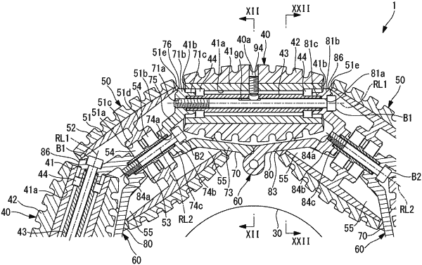
1. An omnidirectional wheel whose outer circumference surface is formed with a plurality of rollers and which rotates around a rotation axis of an axle, the omnidirectional wheel comprising:
a rotating part that rotates around the rotational axis of the axle; and
a plurality of supports which is arranged in a circumferential direction of the rotating part and each of which is mounted on the rotating part to support the plurality of rollers on the rotating part, wherein
the plurality of rollers includes a plurality of first rollers and a plurality of second rollers having a different outside diameter from the first rollers,
the first rollers and the second rollers alternate with each other in the circumferential direction,
each of the supports has a first arm member that supports one end side in an axial direction of a corresponding first roller that is a corresponding one of the plurality of first rollers, and a second arm member that supports the other end side in the axial direction of the corresponding first roller,
a corresponding second roller that is a corresponding one of the plurality of second rollers is supported by the first arm member of one of two supports that are adjacent to each other in the circumferential direction and the second arm member of the other one of the two supports,
one end side in the axial direction of the corresponding first roller is supported by one end side of the first arm member, and the other end side of the first arm member is mounted on the rotating part, and
the other end side in the axial direction of the corresponding first roller is supported by one end side of the second arm member, and the other end side of the second arm member is mounted on the rotating part.
|