| CPC B41J 2/14201 (2013.01) [B41J 2/14072 (2013.01); B41J 2/1607 (2013.01); B41J 2/1623 (2013.01); B41J 2002/14491 (2013.01); B41J 2202/19 (2013.01); B41J 2202/20 (2013.01)] | 8 Claims |

|
1. A liquid ejection head comprising:
a base plate; and
first and second device chips in which ejection ports for ejecting a liquid are formed, the first and second device chips being disposed on the base plate,
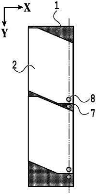
wherein a first reference mark is provided on the base plate,
second reference marks are provided on a surface of each of the first and second device chips, respectively,
the first reference mark and the second reference marks are disposed on an array axis along which the first device chip and the second device chip are arrayed,
a region of the second device chip extending along a side adjacent the first device chip includes a first portion and a second portion, the second portion of the second device chip being provided closer to the first device chip than the first portion of the second device chip is to the first device chip,
a space is formed between the first portion of the second device chip and the first device chip,
the first reference mark is provided in the space, and
the first reference mark and the second reference marks are not in contact with each other.
|