| CPC B41J 2/04581 (2013.01) [B41J 2/04578 (2013.01); B81B 3/0086 (2013.01); B81B 2201/032 (2013.01)] | 9 Claims |

|
1. A droplet jetting device comprising:
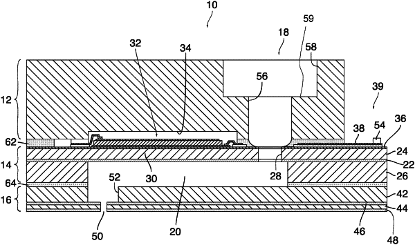
a membrane layer defining a pressure chamber that is in fluid communication with a nozzle, the membrane layer carrying, on a membrane that covers the pressure chamber, an actuator for generating pressure waves in a liquid in the pressure chamber;
a distribution layer bonded to the membrane layer on a side of the membrane and defining a supply line for supplying the liquid to the pressure chamber, the supply line being connected to the pressure chamber via a restrictor passage positioned over the pressure chamber and extending through the distribution layer in the thickness direction of that layer up to the membrane layer, and via a window formed in the membrane, wherein the restrictor passage has a uniform cross-section, and the membrane window is delimited by a contour that is inwardly offset from the contour of the restrictor passage on the entire periphery of the restrictor passage, wherein the ink supply line comprises a trench formed in the surface of the distribution layer, and the restrictor passage extends from the bottom of the trench.
|