| CPC B29C 66/82 (2013.01) [B25J 11/005 (2013.01); B25J 15/0019 (2013.01); B29C 65/32 (2013.01); B29C 66/0342 (2013.01); B29C 66/721 (2013.01); B29C 66/7392 (2013.01); B29K 2307/04 (2013.01); H05B 6/105 (2013.01)] | 15 Claims |

|
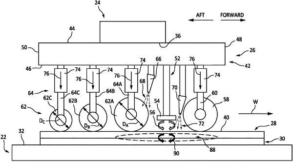
1. An end effector for welding composite components, the end effector comprising:
an end effector housing extending in a welding direction between and to a forward housing end and an aft housing end;
an induction welding member mounted to the end effector housing, the induction welding member including an induction coil;
a leading roller mounted to the end effector housing forward of the induction coil in the welding direction;
at least one follower roller, each follower roller of the at least one follower roller mounted to the end effector housing aft of the induction coil in the welding direction, the at least one follower roller including a first follower roller disposed adjacent the induction welding member such that the induction coil is disposed between the leading roller and the first follower roller in the welding direction; and
at least one first cooling air jet disposed between the induction welding member and the first follower roller in the welding direction, the at least one first cooling air jet positioned to direct a first stream of cooling air toward and onto the first follower roller.
|