| CPC B25J 9/1664 (2013.01) [G01B 21/20 (2013.01); B25J 19/02 (2013.01)] | 8 Claims |
|
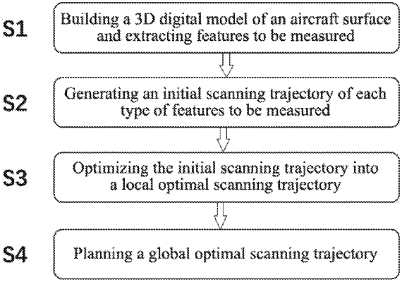
1. A feature-guided scanning trajectory optimization method for a three-dimensional (3D) measurement robot, comprising:
(S1) building a 3D digital model of an aircraft surface; obtaining a size of the 3D digital model; extracting features to be measured from the 3D digital model; and classifying the features to be measured;
(S2) calculating a geometric parameter of each type of features to be measured; and generating an initial scanning trajectory of each type of features to be measured;
(S3) building a constraint model of the 3D measurement robot; and optimizing the initial scanning trajectory of each type of features to be measured into a local optimal scanning trajectory; and
(S4) based on the local optimal scanning trajectory, planning a global optimal scanning trajectory of the features to be measured of the aircraft surface by using a modified ant colony optimization algorithm;
wherein the step (S3) comprises:
(S31) based on a flange coordinate system of the 3D measurement robot, converting a posture change of the 3D measurement robot during a scanning process into changes of scanning depth d, yaw angle α, pitch angle β and rotation angle ω; and building the constraint model of the 3D measurement robot;
(S32) based on the constraint model of the 3D measurement robot, traversing initial scanning trajectories of all types of features to be measured; and constructing a trajectory optimization evaluating function E, expressed as:
E=5×10⁻⁵×√(1.2dmax−d)2×√(ϕ−0.6ϕmin)2+λ+μ√(φ−0.3φmin)2;
wherein ϕ is an out-of-plane angle; φ is an in-plane angle; λ is a penalty factor of the trajectory optimization evaluating function; μ is a penalty factor of the in-plane angle; dmax is a maximum scanning depth; and ϕmin is a minimum out-of-plane angle; and
(S33) repeating the step (S32) successively with the scanning depth, in-plane angle and out-of-plane angle as a single variable to minimize the trajectory optimization evaluating function E, so as to obtain the local optimal scanning trajectory of each type of features to be measured, expressed as:
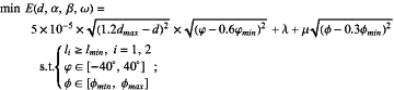 wherein li is an effective scanning width of a 3D measurement scanner; lmin is a width between the initial scanning trajectories; φmin represents a minimum in-plane angle; and φmax represents a maximum in-plane angle.
|