| CPC B25J 15/08 (2013.01) [A01C 11/025 (2013.01)] | 8 Claims |

|
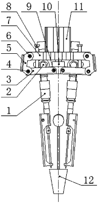
1. An adjustable seedling pick-up end effector for automatically transplanting plug seedlings, comprising two clamping fingers, support frames, and a mechanical arm, wherein
the two clamping fingers are installed symmetrically along a direction of a center line; one end of each of the support frames is connected to an upper end of a respective one of the two clamping fingers, an other end of each of the support frames is connected to a respective one of rockers of the mechanical arm, and a slotted hole is provided on the end of each of the support frames for adjusting a distance between the two clamping fingers;
each of the support frames comprises a cover plate, a support base, locking bolts, a locking nut, and an L-shaped connecting plate; wherein
the cover plate and the support base are respectively arranged on two sides of the upper end of the respective one of the two clamping fingers and are connected by the locking bolts to fasten the respective one of the two clamping fingers; one end surface of the L-shaped connecting plate is provided with the slotted hole, and an other end surface of the L-shaped connecting plate is connected to the respective one of the rockers of the mechanical arm; a connecting end of the support base is passed through the slotted hole and is connected to the L-shaped connecting plate by a tightening of the locking nut;
the mechanical arm comprises connecting rods, the rockers, a bracket, helical limiting rods, a slider, and a linear motion unit; the slider is connected to a movable element of the linear motion unit along the direction of the center line; the connecting rods are respectively arranged on two sides of the slider, one end of each of the connecting rods is hingedly connected to the slider, an other end of each of the connecting rods is hingedly connected to one end of the respective one of the rockers, and an other end of each of the rockers is hingedly connected to the bracket; the helical limiting rods each extend through the bracket in a manner of a helical pair along a direction parallel to the center line and are configured to limit a movement space for closing the connecting rods; when the linear motion unit drives the slider to move upward, the connecting rods drive the rockers to cause the two clamping fingers to close inward; and when the linear motion unit drives the slider to move downward, the connecting rods drive the rockers to cause the two clamping fingers to open outward; and
the mechanical arm is an eccentric slider-rocker mechanism configured to be closed and opened along the center line with the bracket as a stationary frame, the slider as a driving part, and the connecting rods and the rockers as driven parts, and the eccentric slider-rocker mechanism is configured to limit a closure ultimate position of the connecting rods by a limiting function of the helical limiting rods.
|