| CPC B25B 23/005 (2013.01) [E04F 21/22 (2013.01); B25B 21/00 (2013.01)] | 20 Claims |

|
1. A fastener installation tool comprising:
a frame including a first end and a second end;
a stationary handle joined with the frame and adapted to be grasped by a user, the stationary handle projecting from the first end in a cantilevered manner;
a moveable handle joined with the frame and moveable relative to the stationary handle, the moveable handle projecting from the first end in a cantilevered manner and distal from the stationary handle;
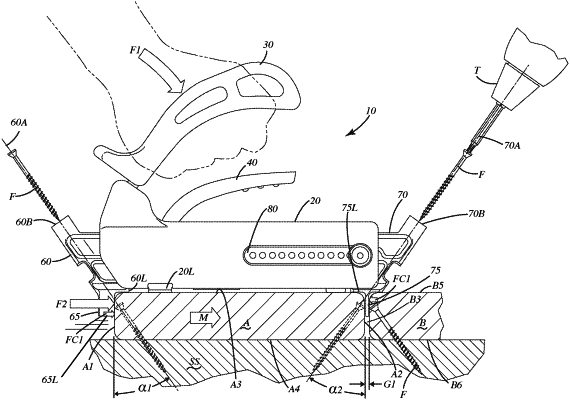
a first guide joined with the frame adjacent the first end, the first guide defining a first angled bore, the first angled bore including a first axis, a first opening adapted to enable a fastener to enter the first angled bore and a second opening adapted to enable the fastener to exit the first angled bore, the first and second openings aligned along the first axis which is adapted to be disposed at a non-orthogonal angle relative to a first side surface of a first workpiece;
a pusher block joined with the first guide, the pusher block projecting downwardly from the first guide a first distance, the pusher block including a pusher block width extending from a first forward face to a first rearward face of the pusher block;
a second guide joined with the frame adjacent the second end in a selectively adjustable manner, the second guide defining a second angled bore, the second angled bore including a second axis that is transverse to the first axis of the first guide, a first opening adapted to enable another fastener to enter the second angled bore and a second opening adapted to enable the other fastener to exit the second angled bore, the first and second openings of the second axis aligned along the second axis which is adapted to be disposed at a non-orthogonal angle relative to a second side surface of the first workpiece, opposite the first side surface;
a spacer joined with the second guide, the spacer projecting downwardly from the second guide a second distance, the spacer including a spacer width extending from a second forward face to a second rearward face, the spacer width of the spacer being less than the pusher block width of the pusher block,
wherein the spacer faces toward the first side surface of the first workpiece such that the spacer width establishes and sets a gap width of a first gap, the gap width substantially equal to the spacer width, between the second side surface of the first workpiece and a third side surface of a second workpiece when the first workpiece is fastened to an underlying substrate,
wherein the pusher block faces toward the first side surface of the first workpiece and projects away from the first side surface of the first workpiece by the pusher block width,
wherein the pusher block width is incapable of establishing and setting a second gap adjacent the second side surface of the second workpiece that is a same gap width as the first gap after the first and second workpieces are fastened to a substrate because the pusher block width is greater than the spacer width.
|