| CPC B23K 26/21 (2015.10) [B23K 26/046 (2013.01); B23K 26/0643 (2013.01); B23K 26/0648 (2013.01); B23K 26/0652 (2013.01); B23K 26/073 (2013.01)] | 9 Claims |

|
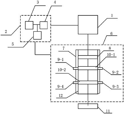
1. A laser fusion welding device, comprising a 1.9 μm laser light source, a control unit and a light spot adjusting device, wherein the control unit is configured to control the 1.9 μm laser light source and the light spot adjusting device to adjust a laser power density at an object to be subjected to fusion welding;
the 1.9 μm laser light source has output power of 100 W-500 W;
the control unit comprises a time control unit, a power control unit and a light spot control unit, wherein the time control unit is configured to control a turn-on time of the 1.9 μm laser light source, the power control unit is configured to control the output power of the 1.9 μm laser light source, and the light spot control unit is configured to control the light spot adjusting device to adjust a size of a light spot at the object to be subjected to fusion welding; and
the light spot adjusting device comprises a lens barrel, an electric slideway axially arranged along an inner side wall of the lens barrel, and a plurality of optical lenses arranged in the lens barrel, and the light spot control unit is configured to control a distance between the plurality of optical lenses through the electric slideway to adjust the size of the light spot at the object to be subjected to fusion welding;
the 1.9 μm laser light source comprises a resonant cavity and n discontinuous laser crystals located in the resonant cavity, wherein the resonant cavity comprises a total reflection mirror and an output mirror, the total reflection mirror is coated with a 1.9 μm high-reflection film layer, the output mirror is coated with a film layer having a transmittance of 10% for 1.9 μm, the n discontinuous laser crystals are all Tm: yttrium aluminum perovskite (YAP), and the n discontinuous laser crystals are in a side pumping mode; and
side faces of the n discontinuous laser crystals are provided with n semiconductor pumping light sources in a one-to-one relationship, a sum of angles of the n semiconductor pumping light sources surrounding the n discontinuous laser crystals is 360°, and n is a natural number greater than or equal to 4.
|