| CPC B23K 26/142 (2015.10) [B23K 26/123 (2013.01); B23K 26/127 (2013.01); B23K 26/147 (2013.01); B23K 26/064 (2015.10); B23K 26/21 (2015.10)] | 12 Claims |

|
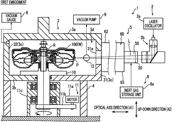
1. A laser welding device comprising:
a chamber that has a low-pressure internal space in which a workpiece is disposed;
a laser beam irradiation unit that irradiates the workpiece with a laser beam to weld the workpiece;
a laser transmission window through which the laser beam from the laser beam irradiation unit is transmitted; and
a gas injection nozzle that is disposed on a workpiece side from the laser transmission window,
wherein the gas injection nozzle includes an optical path hole through which the laser beam passes and an injector that injects an inert gas for shielding metal vapor, which is ejected from the workpiece to the laser transmission window side when the workpiece is welded by the laser beam, into the optical path hole toward an irradiation direction side and an optical axis side of the laser beam, and
wherein the injector is provided in a circumferential shape along an inner peripheral surface of the optical path hole.
|