| CPC B23B 29/046 (2013.01) [F16B 2/065 (2013.01); F16B 2/18 (2013.01); Y10T 403/7067 (2015.01)] | 27 Claims |

|
1. A tool coupling (20) extending in a forward-to-rearward direction (DF, DR) along a longitudinal axis (A1), and having a first plane (P1) perpendicular to the longitudinal axis (A1) and a second plane (P2) containing the longitudinal axis (A1) and transverse to the first plane (P1), the second plane (P2) having an upper side (SU) defining an upward direction (DU) of the tool coupling (20) and a lower side (SL) which is opposite to the upper side (SU) and defines a downward direction (DD) of the tool coupling (20), the tool coupling (20) comprising:
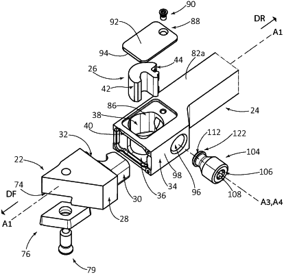
a first component (22), a second component (24), and a clamp (26) for fastening the first component (22) to the second component (24),
the first component (22) having a first body portion (28) and a male clamping portion (30) extending from a rear mating end (32) of the first body portion (28) in the rearward direction (DR),
the second component (24) having a second body portion (34), a female clamping portion (36), and an inner cavity (38), the female clamping portion (36) opening out to a forward mating end (40) of the second body portion (34) and the inner cavity (38) communicating with the female clamping portion (36), and
the clamp (26) located in the inner cavity (38) and having a clamp forward engagement portion (42) and a clamp rear drive portion (44), the clamp forward engagement portion (42) having a clamp first engagement region (62) and a clamp second engagement region (64), wherein:
the male clamping portion (30) occupies the female clamping portion (36) and has a first abutment region (46) located axially rearward of the first plane (P1);
the inner cavity (38) has a second abutment region (48) located axially forward of the first plane (P1), the second abutment region (48) being located on the upper side (SU) of the second plane (P2);
each of the first and second abutment regions (46, 48) faces towards the first plane (P1); and
in a fastened state of the tool coupling (20):
a rear mating surface (58) of the rear mating end (32) makes clamping contact with a forward mating surface (60) of the forward mating end (40);
the clamp first engagement region (62) makes clamping contact with the male clamping portion's first abutment region (46); and
the clamp second engagement region (64) makes clamping contact with the inner cavity's second abutment region (48).
|