| CPC B01L 3/50853 (2013.01) [G01N 1/10 (2013.01); G01N 15/06 (2013.01); G01N 21/01 (2013.01); G01N 21/0303 (2013.01); G01N 21/274 (2013.01); G01N 21/4738 (2013.01); G01N 21/4785 (2013.01); G01N 21/51 (2013.01); G01N 21/5907 (2013.01); G01N 21/8806 (2013.01); G01N 21/93 (2013.01); G01N 33/487 (2013.01); G01N 33/48735 (2013.01); B01L 2200/14 (2013.01); B01L 2300/0654 (2013.01); B01L 2300/0803 (2013.01); B01L 2300/12 (2013.01); G01N 2015/0693 (2013.01); G01N 2021/0168 (2013.01); G01N 2021/0389 (2013.01); G01N 21/474 (2013.01); G01N 2021/4769 (2013.01); G01N 2021/598 (2013.01); G01N 2201/126 (2013.01); G01N 2201/12707 (2013.01)] | 17 Claims |

|
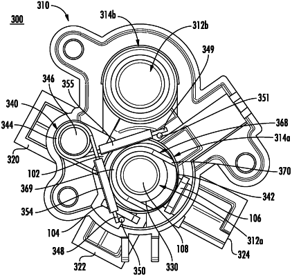
1. An apparatus for facilitating the optical interrogation of a test sample, the apparatus comprising:
a shell defining:
a cavity for receiving at least a portion of a sample tube; and
a pair of apertures, wherein each aperture in the pair of apertures is configured to optically couple the cavity with an exterior of the shell;
a pair of windows each of which is disposed across a respective one of the pair of apertures, wherein the pair of windows are substantially perpendicular to one another;
an emitter disposed outside the cavity, the emitter configured to emit electromagnetic radiation through a first window of the pair of windows disposed across a first aperture of the pair of apertures and into the cavity; and
a second detector disposed outside the cavity, the second detector configured to receive a portion of the electromagnetic radiation through a third window of the pair of windows disposed across a third aperture of the pair of apertures from the cavity, wherein the second detector comprises a nephelometric sensor;
a spring configured to apply a force on the sample tube in the instance in which the cavity receives the portion of the sample tube; and
a roller disposed about a leg of the spring, such that the roller is configured to rotate about the leg of the spring in an instance in which the sample tube is being inserted into the cavity and/or removed from the cavity.
|
|
17. An apparatus for facilitating the optical interrogation of a test sample, the apparatus comprising:
a shell defining:
a cavity for receiving at least a portion of a sample tube;
a pair of apertures, wherein each aperture in the pair of apertures is configured to optically couple the cavity with an exterior of the shell;
a sealed distal end; and
a proximal end opposite the sealed distal end, the proximal end defining an opening configured to removably receive the portion of the sample tube therethrough;
a pair of windows each of which is disposed across a respective one of the pair of apertures, wherein the pair of windows are substantially perpendicular to one another;
a spring configured to apply a force on the sample tube in the instance in which the cavity receives the portion of the sample tube, wherein the force is applied perpendicular to an axis extending between the sealed distal end and the proximal end; and
a roller disposed about a leg of the spring, such that the roller is configured to rotate about the leg of the spring in an instance in which the sample tube is being inserted into the cavity and/or removed from the cavity.
|