| CPC B01F 23/2362 (2022.01) [B01F 33/821 (2022.01); B01F 23/2364 (2022.01); B01F 25/25 (2022.01); B01F 33/834 (2022.01); B67D 1/0058 (2013.01); B67D 1/0071 (2013.01)] | 12 Claims |

|
1. A carbonized water dispensing device comprising:
a carbonized water dispensing outlet, for dispensing carbonized water into a beverage container;
a cold water source;
a CO2 source;
a water line, the water line extending between the cold water source and a dispensing outlet;
a water carbonation system comprising an in-line carbonator for adding CO2 from the CO2 source to the water flowing through the water line from the cold water source to the dispensing outlet,
wherein the in-line carbonator comprises:
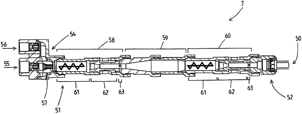
a tubular conduit disposed about a longitudinal axis, extending from an input end to and output end, and defining a fluid flow path from the input end to the output end;
an inlet manifold comprising a first inlet for water, a second inlet for carbon dioxide, and an outlet in fluid communication with the input end of the conduit;
wherein the conduit comprises a first treatment trajectory directly followed by a conditioning trajectory directly followed by a second treatment trajectory, such that the water subsequently flows from the first treatment trajectory into the conditioning trajectory into the second treatment trajectory;
wherein each treatment trajectory comprises:
a helical dispersion element disposed in the conduit and having an axis aligned with the longitudinal axis of the conduit;
a passive accelerator located immediately downstream of the helical dispersion element, wherein the passive accelerator comprises a restriction portion of the conduit having a reduced cross sectional area relative to portions of the conduit immediately upstream and downstream of the restriction portion;
a rigid impact surface immediately downstream of the passive accelerator, which rigid impact surface is disposed perpendicular to the longitudinal axis of the conduit; and
wherein the conditioning trajectory comprises:
a conditioning conduit extending between the first and second treatment trajectories, the conditioning conduit having an axis aligned with the longitudinal axis of the conduit.
|