| CPC A62C 37/09 (2013.01) [B05B 1/265 (2013.01); B05B 1/267 (2013.01); A62C 37/11 (2013.01); A62C 37/14 (2013.01)] | 18 Claims |

|
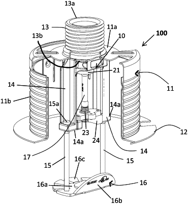
1. A concealable sprinkler head comprising:
a sprinkler frame comprising:
a body mountable to a fire suppression liquid source, the body defining a proximal inlet, a distal outlet and an internal fire suppression liquid passageway extending therethrough;
a pair of frame arms extending away from the body; and
a pair of corresponding drop pins each being slidably engaged with a respective frame arm;
a sealing plug positioned in a sealing position to seal the internal fire suppression liquid passageway, maintaining the sprinkler head in a non-spraying state;
a thermal trigger supported within the sprinkler frame and operatively engaged with the sealing plug and configured to release the sealing plug from the sealing position upon activation of the thermal trigger,
a fluid deflector secured to the pair of drop pins;
a concealing cup having an upper wall attached to, and laterally outwardly projecting from, the body of the sprinkler frame, a skirting side wall extending away from the upper wall, and an open base end, the pair of frame arms being at least partially positioned within the concealing cup; and
a cover plate attached to the concealing cup, covering at least a portion of the open base end of the concealing cup and maintaining the pair of drop pins and the fluid deflector in a compressed, non-activated position,
wherein, in the compressed, non-activated position:
the fluid deflector includes an at least partially planar surface having a periphery, the pair of drop pins extending from the at least partially planar surface and defining an axis extending through the pair of drop pins, and an inclined surface extending angularly upwardly toward the sprinkler frame from a portion of the periphery of the at least partially planar surface located along one side of the axis, and
at least a portion of the cover plate being removable from the concealing cup at a predetermined temperature, permitting the pair of drop pins and the deflector to drop down relative to the compressed, non-activated position into an extended operational position wherein the inclined surface is configured to direct fire suppression liquid to an opposing side of the axis.
|