| CPC A61B 17/07207 (2013.01) [A61B 2017/00017 (2013.01); A61B 2017/00115 (2013.01); A61B 2017/0019 (2013.01); A61B 2017/0023 (2013.01); A61B 2017/00398 (2013.01); A61B 2017/00407 (2013.01); A61B 2017/0042 (2013.01); A61B 2017/0046 (2013.01); A61B 2017/00734 (2013.01); A61B 2017/07271 (2013.01); A61B 2017/07285 (2013.01); A61B 2017/2923 (2013.01); A61B 2017/2925 (2013.01); A61B 2017/2927 (2013.01); A61B 2017/2946 (2013.01); A61B 2018/00297 (2013.01); A61B 2090/064 (2016.02); A61B 2090/0807 (2016.02); A61B 2090/0811 (2016.02); A61B 2090/0814 (2016.02)] | 15 Claims |

|
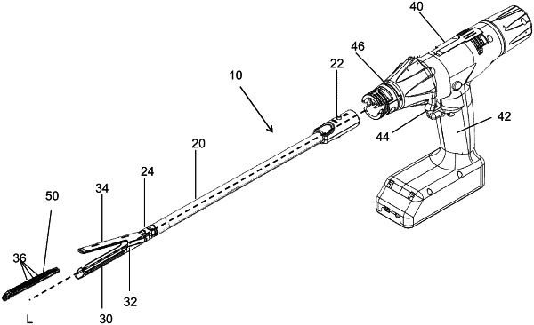
1. A handle assembly for a surgical stapler, the handle assembly comprising:
a handle body, the handle body comprising a stationary handle and a trigger pivotably coupled to the handle body;
an electric motor disposed within the handle body;
a control system disposed within the handle body and coupled to the electric motor, wherein the control system is configured to control an operation of the electric motor;
an actuation shaft having a distal end and a proximal end, wherein the actuation shaft is slidable within the handle body along a longitudinal axis; and
a lockout mechanism that is operably coupled to the distal end of the actuation shaft, wherein the lockout mechanism has at least one notch corresponding to a lockout region,
wherein the control system comprises computer-readable memory that configures the control system to:
monitor a position of the actuation shaft,
monitor a current draw from the electric motor,
calculate a rate of change of the current draw from the electric motor, and
adjust an operation of the electric motor based on the monitored position and the calculated rate of change of the current draw, wherein the electric motor is depowered when the position of the actuation shaft is at a predetermined location and the calculated rate of change of the current draw is equal to or exceeds a predetermined threshold, and
wherein a lockout condition associated with the lockout mechanism is detected after calculating the rate of change of the current draw a pre-determined number of times consecutively, and wherein an average of each of the consecutively calculated rate of changes of the current draw fall within a predetermined range.
|