| CPC H02M 1/14 (2013.01) [H01F 17/04 (2013.01); H01F 37/00 (2013.01); H02M 3/003 (2021.05); H02M 7/003 (2013.01)] |

| AS A RESULT OF REEXAMINATION, IT HAS BEEN DETERMINED THAT: |
| The patentability of claims 16-21 and 23-28 is confirmed. |
| Claims 1-3, 5, 10 and 12-15 are cancelled. |
| Claims 4, 6-9, 11, 22 and 29 were not reexamined. |
|
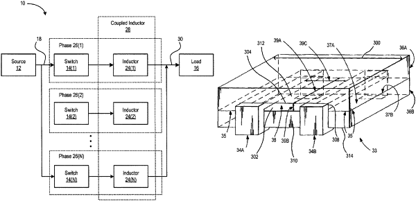
16. A two phase DC-to-DC converter, comprising:
a two phase coupled inductor, including:
a magnetic core forming a passageway, the passageway having depth and height defining a cross-sectional area of the passageway, and
a first and a second winding having a same number of turns wound at least partially around a common leg of the magnetic core and through the passageway, the first and second windings separated by a linear separation distance throughout the passageway the separation distance being along an axis perpendicular to an axis of the height of the passageway and perpendicular to an axis of the depth of the passageway, each winding having a respective first end and a respective second end, the second ends of the first and second windings being electrically connected to a common load, the cross-sectional area of the passageway between the windings being at least 50% free of magnetic material;
a first switch electrically connected between a power source and the first end of the first winding; and
a second switch electrically connected between the power source and the first end of the second winding;
wherein the first and second switches independently and sequentially switch the first end of their respective winding to an input signal of the power source to regulate an output signal at the load.
|