| CPC F01N 3/055 (2013.01) [F01N 13/10 (2013.01); F01P 1/02 (2013.01); F01P 1/06 (2013.01); F01N 2240/20 (2013.01); F01P 2001/023 (2013.01)] | 20 Claims |

|
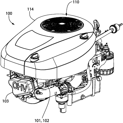
1. An engine assembly comprising:
an engine comprising a plurality of cooling fins;
a blower configured to blow air through an air flow path;
an exhaust header having an inlet end configured to receive exhaust gas from the engine;
a muffler fluidly coupled to an outlet end of the exhaust header; and
an air control baffle joined to the engine to define the airflow path, the plurality of cooling fins located within the air flow path;
wherein the air flow path is configured to direct a portion of the air from the blower towards the exhaust header and the muffler, the portion of the air passing over the plurality of cooling fins before being directed towards the exhaust header and the muffler.
|