| CPC A44B 11/266 (2013.01) [A44B 11/2592 (2013.01)] | 10 Claims |

|
1. A pluggable connecting buckle, comprising a male buckle and a female buckle, wherein
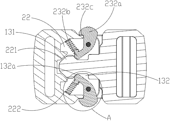
a first connecting rod is arranged on one end of the male buckle, a decorative plate and a buckling rib protruding from an inner side of the decorative plate are arranged on an other end of the male buckle, a buckling block is arranged on an end of the buckling rib away from the first connecting rod, and a corresponding engagement groove is arranged on each of two sides of the buckling rib; and
a second connecting rod is arranged on one end of the female buckle, an accommodating cavity with an outer open end is arranged on an other end of the female buckle, a blocking block engaged with the buckling block is arranged on an inner end of the accommodating cavity, two corresponding engagement assemblies are respectively arranged on two sides of the accommodating cavity, a limiting plate is arranged on an outer side of each of the engagement assemblies, each engagement assembly comprises a riveting shaft perpendicular to a buckling direction, a turning plate rotatably connected to the riveting shaft, and a spring arranged on the turning plate, one end of the turning plate protruding from the limiting plate is a turning end, an other end of the turning plate configured to abut against the engagement groove is an engagement end, an inclined engagement surface that does not hinder rotation of the engagement end is arranged on a side of the engagement groove close to the buckling block, the spring is arranged on the engagement end, a spring limiting block corresponding to the spring is arranged on the inner end of the accommodating cavity, a notch engaged with the turning end is arranged on the limiting plate, and an inverted hook plane corresponding to the limiting plate is arranged on the turning end.
|