| CPC H05K 1/0245 (2013.01) [H01R 12/7076 (2013.01); H01R 12/79 (2013.01); H05K 1/0277 (2013.01); H05K 1/115 (2013.01); H05K 1/14 (2013.01); H04N 25/70 (2023.01); H05K 2201/10189 (2013.01)] | 11 Claims |

|
1. A signal transmission apparatus comprising:
a flexible printed circuit board having signal transmission paths for transmitting a differential signal,
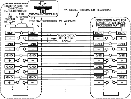
wherein at least one of connector connection parts of the flexible printed circuit board has a first connection part column and a second connection part column obtained by arranging a plurality of signal line connection parts, the signal line connection parts being connection parts between the signal transmission paths and intra-connector wiring as two column lines in parallel with each other, and
each of the signal line connection parts formed in the first connection part column and in the second connection part column is configured to be connected with the signal transmission path formed on a back side of the flexible printed circuit board by way of a VIA (through-hole) formed between the first connection part column and the second connection part column.
|