| CPC F16K 27/02 (2013.01) [F16K 31/1221 (2013.01); F16K 31/1226 (2013.01)] | 20 Claims |

|
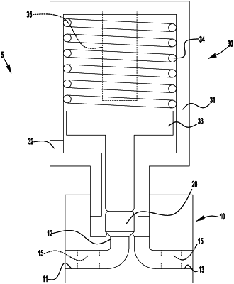
1. An actuated valve assembly comprising:
a valve body including a valve seat disposed between inlet and outlet passages, and a fixed orifice restriction provided in at least one of the inlet and outlet passages;
a valve element assembled with the valve body and axially movable between a closed position in sealing engagement with the valve seat, to block flow between the inlet and outlet passages, and an open position spaced apart from the valve seat to permit flow between the inlet and outlet passages;
an actuator assembled with the valve body and connected with the valve element for axial movement of the valve element between the closed and open positions; and
a stroke adjustment mechanism operable to adjust the open position from a maximum open position to a reduced open position to limit the movement of the valve element to adjust a seat annulus flow area associated with the valve seat and valve element from a maximum seat annulus flow area in the maximum open position to a reduced seat annulus flow area in the reduced open position;
wherein the actuated valve assembly has an effective flow coefficient based on a first flow coefficient of the fixed orifice restriction and a second flow coefficient of a remainder of the actuated valve assembly without the fixed orifice restriction;
wherein a ratio of the second flow coefficient to the first flow coefficient is between 3:2 and 4:1 when the valve element is in the maximum open position, corresponding to a maximum effective flow coefficient; and
wherein the fixed orifice restriction is sized such that operation of the stroke adjustment mechanism to reduce the second flow coefficient by one half provides at least an 8% reduction in the effective flow coefficient from the maximum effective flow coefficient.
|