| CPC F04D 29/584 (2013.01) [F04D 19/042 (2013.01); F04D 29/522 (2013.01); F04D 29/644 (2013.01); F04D 29/684 (2013.01)] | 12 Claims |

|
1. A vacuum pump comprising:
a rotor formed with multiple stages of rotor blades and a rotor cylindrical portion;
a stator formed with multiple stages of stationary blades and a stator cylindrical portion arranged with a predetermined gap from the rotor cylindrical portion;
a housing including: a first pump case in which the rotor blades and the stationary blades are arranged, a second pump case in which the rotor cylindrical portion and the stator cylindrical portion are arranged, and a base;
a first heating section configured to heat the stator cylindrical portion to a temperature for reducing product accumulation;
an exhaust pipe provided at the second pump case storing the rotor cylindrical portion and the stator cylindrical portion to discharge gas discharged by the rotor and the stator to an outside of the second pump case;
a second heating section configured to heat the exhaust pipe to a temperature for reducing product accumulation; and
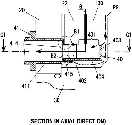
a gas passage container preventing product accumulation on the second pump case and the base, the gas passage container being formed of a discrete body with U-shaped cross section constituted by an outer peripheral wall covering an inner peripheral wall of the second pump case, an inner peripheral wall covering an outer peripheral wall of the base, and a bottom wall covering a bottom surface of the base, having an inlet port at an opening of the U-shaped body into which gas discharged through the predetermined gap between the rotor cylindrical portion and the stator cylindrical portion flows and an outlet port in the outer peripheral wall from which inflow gas flows to the exhaust pipe, and heated to a temperature for reducing product accumulation,
wherein a gas-inflow-side end portion of the exhaust pipe is inserted into the outlet port of the gas passage container through a clearance.
|