| CPC F04C 25/02 (2013.01) [F04C 18/3441 (2013.01); F04C 29/126 (2013.01); F04C 29/128 (2013.01); F04C 2220/10 (2013.01); F04C 2240/30 (2013.01)] | 16 Claims |
|
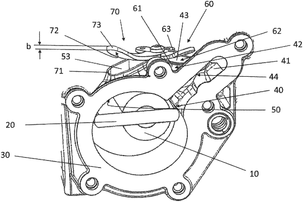
1. A vacuum pump for supplying a machine assembly with negative pressure, the vacuum pump comprising:
1.1 a housing featuring:
1.1.1 a delivery chamber which comprises a chamber inlet opening and a chamber outlet opening for a gaseous fluid;
1.1.2 a suction port for establishing a fluid connection to the machine assembly;
1.1.3 a suction channel which emerges into the delivery chamber via the chamber inlet opening and connects the delivery chamber to the suction port; and
1.1.4 a relief channel which connects the delivery chamber to a relief opening of the housing;
1.1.5 a discharge opening connected to the chamber outlet opening;
1.2 a delivery member which can rotate in the delivery chamber in a forward rotational direction and a reverse rotational direction, wherein the fluid is suctioned into the delivery chamber through the chamber inlet opening and discharged through the chamber outlet opening by rotating the delivery member in the forward rotational direction; and
1.3 a relief valve for closing the relief opening when the delivery member rotates in the forward rotational direction and opening the relief opening when the delivery member rotates in the reverse rotational direction,
1.4 a main valve in order to prevent the fluid from being suctioned through the discharge opening when the delivery member rotates in the reverse rotational direction and to allow the fluid to be discharged through the discharge opening when the delivery member rotates in the forward rotational direction,
1.5 wherein the relief channel emerges into the suction channel, and
1.6 wherein the relief valve and the main valve are each formed as a reed valve comprising a spring-elastic valve tongue and an abutment for the valve tongue,
1.7 wherein the valve tongue of the relief valve and the valve tongue of the main valve are connected to each other via a common fastening region,
1.8 wherein the valve tongues are connected in an L shape via the common fastening region and are produced in one piece, and protrude, as viewed in a plan view, from the common fastening region at an enclosed angle α,
1.9 wherein α is 90° with a deviation at most of ±20° , and
1.10 wherein the relief valve and the main valve together form a double reed valve, and
1.11 wherein the valve tongue of the main valve, as viewed in a plan view, is wider than the valve tongue of the relief valve.
|