| CPC C30B 35/007 (2013.01) [C30B 23/002 (2013.01); C30B 23/025 (2013.01); C30B 23/063 (2013.01)] | 20 Claims |

|
1. A molecular-beam epitaxy (MBE) system, comprising:
(a) an ultra-high vacuum (UHV) chamber;
(b) a heater consisting of infrared radiation (IR) emitting heater;
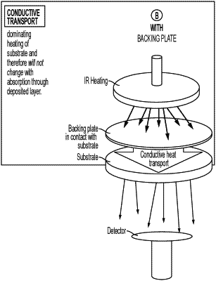
(c) a thermally conductive backing plate including a first surface and a second surface;
(d) an infrared-absorbing coating (IAC) deposited onto at least the first surface of the thermally conductive backing plate;
(e) a substrate having a first bandgap positioned on the second surface of the thermally conductive backing plate;
(f) at least one effusion cell directed towards the substrate; and
(g) an MBE-film grown onto an outer surface of the substrate, the MBE-film having a second bandgap and comprises one or more chalcogenides;
wherein the IAC absorbs from 70 to 100% of radiant heat from the IR emitting heater and transfers the radiant heat to the substrate via thermal conduction,
wherein the IR emitting heater is located (i) inside the UHV chamber and (ii) separately from the thermally conductive backing plate, and wherein the IR emitting heater is configured to emit IR directly onto the IAC, and
wherein the first bandgap is larger than the second bandgap.
|