| CPC B60S 9/04 (2013.01) | 13 Claims |

|
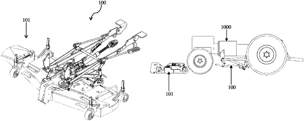
1. A mounting mechanism configured to enable hitching a tool with a frame of a utility vehicle, said mounting mechanism comprising:
front hooks configured to be detachably coupled to operative front portion of said tool;
a locking mechanism configured to detachably engage with the rear portion of said tool, said front hooks and said locking mechanism configured to form part of said tool;
a lifting cradle assembly comprising a front horizontal rod and a rear horizontal rod, said front horizontal rod configured to be operatively engaged with said front hooks and said rear horizontal rod configured to be operatively engaged with said locking mechanism; and
a frame attachment mechanism configured to be pivotally coupled to said lifting cradle assembly, said frame attachment mechanism configured to be attached to the vehicle bottom portion, wherein said locking mechanism is configured to be operated by lifting said cradle assembly via pivotal motion between said cradle assembly and said frame attachment mechanism under force generated by said vehicle to engage said cradle assembly with said front hooks and said locking mechanism, and operate said locking mechanism while lifting said tool under force generated by said vehicle, thereby securely locking and hitching said tool with the frame of said vehicle;
wherein said locking mechanism includes:
a release lever having two operative ends with a notch configured on at least one end thereof;
a first U-shaped guide plate having a through slot configured thereon;
a second U-shaped guide plate having a through slot configured thereon, each guide plate includes a plurality of pins extending therefrom, said operative ends of said lever are received by said through slots of said first guide plate and second guide plate respectively;
a first locking plate having a first slot and a second locking plate having a second slot operatively engaged with said first guide plate and said second guide plate respectively;
a spring operatively coupled with at least one of said plates and further configured to lock said plates upon displacement of said plates with respect to said first and second U-shaped guide plates; and
a push spring actuator operatively disposed with each of said locking plates, said push spring actuator configured to hold said locking plates in open position and prevent free motion of said plates.
|