| CPC B23C 3/34 (2013.01) [B23C 3/02 (2013.01); B23Q 9/0035 (2013.01); B23C 2220/36 (2013.01); B23C 2270/18 (2013.01); F05D 2230/10 (2013.01); Y10T 409/304424 (2015.01); Y10T 409/30644 (2015.01)] | 12 Claims |

|
1. A milling device for machining a slot into an inner surface of a casing for a gas turbine engine, comprising:
a frame assembly comprising a plurality of structural guides configured to engage structural features on the inner surface of the casing to maintain an axial position of the milling device relative to a longitudinal axis of the casing; and
a milling cutter coupled to the frame assembly;
wherein the milling device is configured to be displaced in a circumferential direction relative to the longitudinal axis to machine the slot, via the milling cutter, along the inner surface of the casing in the circumferential direction,
wherein the frame assembly is adjustable in both an axial direction and a radial direction relative to the longitudinal axis of the casing;
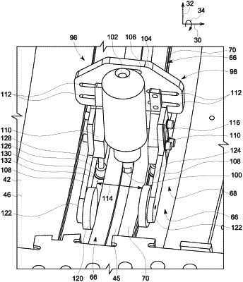
wherein the frame assembly further comprises a plate oriented in the radial direction, a pair of support brackets coupled to the plate, and a pair of support arms coupled to the plate via the pair of support brackets, and both the pair of support brackets and the pair of support arms extend away from the plate, wherein the milling cutter is coupled to the plate, and wherein both the pair of support brackets and the pair of support arms flank the plate;
wherein the frame assembly is adjustable in size; and
wherein the plate comprises a first set of slots and a second set of slots flanking the milling cutter, the pair of support brackets comprises a first support bracket and a second support bracket, the first support bracket and the second support bracket are respectively coupled to the first set of slots and the second set of slots, and a width between the pair of support arms in the axial direction is configured to be adjusted via adjusting respective positions of the pair of support brackets along the first set of slots and the second set of slots.
|