| CPC B21F 3/04 (2013.01) [B21F 9/002 (2013.01); B21F 45/00 (2013.01); H01F 41/04 (2013.01); H01F 41/082 (2016.01); A24F 40/70 (2020.01)] | 9 Claims |

|
1. A coil winding apparatus, comprising:
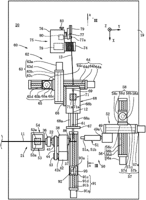
a core rod feeding unit configured to feed a string-shaped core rod from a core rod nozzle at a constant tension;
a core rod drawing unit configured to draw out the core rod from the core rod nozzle against the tension by holding the core rod that has been fed from the core rod nozzle;
a wire rod feeding unit configured to feed a wire rod towards the core rod that has been drawn out from the core rod nozzle, the wire rod being fed in a direction intersecting with a drawing direction of the core rod;
a rotator into which the core rod nozzle is inserted, the rotator being capable of rotating about the core rod nozzle;
a guide member provided on an end portion of the rotator at a position away from a position of an axis of rotation of the rotator, the guide member being configured to clamp, with the core rod, the wire rod that has been fed from the wire rod feeding unit; and
a rotating unit configured to rotate the rotator together with the guide member so as to revolve the wire rod around the core rod in a vicinity of the core rod nozzle, wherein:
the wire rod feeding unit includes:
a wire rod nozzle configured to feed the wire rod to pass therethrough;
a wire rod clamping tool configured to releasably clamp the wire rod passing through the wire rod nozzle; and
a fluid pressure cylinder including a main body portion and a retracting rod, the retracting rod projecting from the main body portion and having the wire rod nozzle mounted thereto, the retracting rod moving in a moving direction with respect to the main body portion, the fluid pressure cylinder being configured to increase and reduce a distance between the wire rod nozzle and the wire rod clamping tool by moving the retracting rod in the moving direction.
|