| CPC B01F 23/232 (2022.01) [B01F 23/2373 (2022.01); B01F 25/103 (2022.01); B01F 25/4323 (2022.01); B01F 25/4335 (2022.01); B01F 2025/913 (2022.01); B01F 2025/916 (2022.01)] | 10 Claims |

|
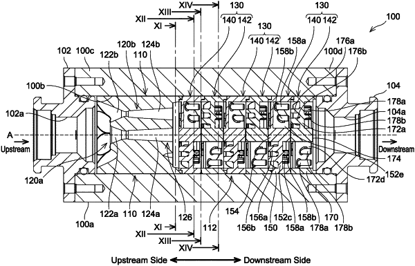
1. A fine bubble generator comprising:
an inlet into which gas-dissolved water in which gas is dissolved flows;
an outlet out of which the gas-dissolved water flows;
a first fine bubble generation portion disposed between the inlet and the outlet; and
a second fine bubble generation portion disposed between the first fine bubble generation portion and the outlet,
wherein the first fine bubble generation portion comprises:
a diameter-reducing flow path, wherein a flow path diameter of the diameter- reducing flow path reduces from upstream to downstream, and
a diameter-increasing flow path disposed downstream of the diameter reducing flow path, wherein the flow path diameter of the diameter-increasing flow path increases from upstream to downstream,
the second fine bubble generation portion comprises:
a first swirling flow generation portion; and
a second swirling flow generation portion disposed downstream of the first swirling flow generation portion,
wherein the first swirling flow generation portion comprises:
a first outer peripheral portion; and
a plurality of first vanes disposed inside the first outer peripheral portion and configured to generate a first swirling flow flowing in a first swirling direction with respect to a center axis of the second fine bubble generation portion, wherein each of the plurality of first vanes has a first upstream-side protrusion protruding to an upstream side or a first downstream-side protrusion protruding to a downstream side or a combination thereof, wherein the first upstream- side protrusion is disposed on an upstream-side surface of the first vane, and wherein the first downstream-side protrusion is disposed on a downstream-side surface of the first vane, and
wherein the second swirling flow generation portion comprises:
a second outer peripheral portion; and
a plurality of second vanes disposed inside the second outer peripheral portion and configured to generate a second swirling flow flowing in a second swirling direction opposite to the first swirling direction with respect to the center axis, wherein each of the plurality of second vanes has a second upstream-side protrusion protruding to the upstream side or a second downstream-side protrusion protruding to the downstream side or a combination thereof, wherein the second upstream-side protrusion is disposed on an upstream-side surface of the second vane, and wherein the second downstream-side protrusion is disposed on a downstream-side surface of the second vane.
|